Self Test Function (continued)
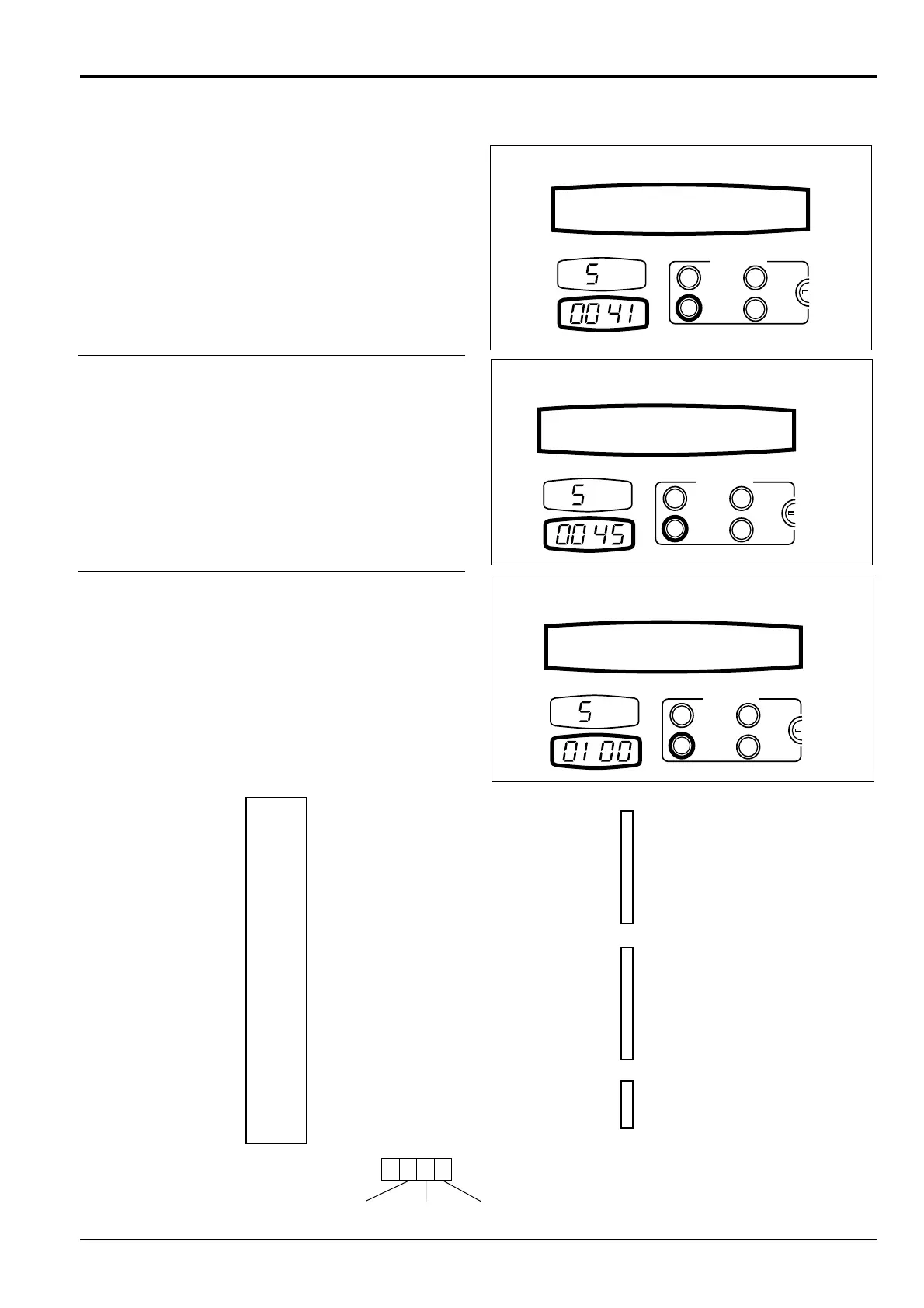
Pressing SELECT changes the display as shown.
The fuel sensor resistance is shown in Ohms in the clock
display.
Pressing SELECT changes the display as shown.
A value of 0 to a maximum of 4.5 Volts will be displayed in
the clock display depending on the position of the throttle.
Pressing SELECT changes the display as shown.This
monitors transistor block output.
When TR is displayed, pressing the reset button once will
initiate the controller to test all the transistor block outputs 1
through 20. If a faulty output is detected it will stop at that
output number. Monitor will display “ELEC. PROBLEM”
(short circuits only).
To detect open circuits, select different services in turn and
check screen display:
e.g. ‘1’ = closed circuit
‘0’ = open circuit
8 - 4
Section C Electrics
9803/6410
Section C
8 - 4
Issue 1
Self Test
1 Free swing solenoid valve
2 2 stage MRV control solenoid valve
3 Low flow hydraulic circuit
4 Servo isolator solenoid valve
5 Slew shut off solenoid valve
6 Not used
7 Not used
8 Not used
9
Boom lower speed restriction solenoid valve
10 Not used
11 Slew lock solenoid valve
12 Max flow cut solenoid valve
13 Cushion solenoid valve
14 Not used
15 Not used
16 Negative control solenoid valve
17 Battery relay
18 Glow plug relay
19 Slew brake solenoid
20 2 speed travel solenoid valve
T
R
A
N
S
I
S
T
O
R
O
U
T
P
U
T
N
U
M
B
E
R
S
C
O
N
T
R
O
L
L
E
R
Block 1
Block 2
Block 3
Block 3
101
Block 1Block 2
JS02480
0 = Output off, 1 = Output on

 Loading...