TACHOMETER CIRCUIT
TEST
IMPORTANT: The tachometer circuit
is
driven
by the stator output. Before proceeding, check
condition of the stator and do the
Stator
Resis-
tance Tests
on
p.
86.
Inspect all engine and boat wiring and make sure
connectors are
in
good condition.
Do
the following tests if the tachometer does not
operate.
STEP 1
Set peak-reading
voltmeter to "POS" and "50."
Check voltage at the battery.
• Use this reading as the reference for battery
voltage.
STEP
2
Check for battery voltage between the tachometer
purple lead and black lead at the dash with the
engine
NOT running and the key switch ON.
• If
the voltmeter shows battery voltage, go to
STEP
3.
• If the voltmeter shows less than battery voltage,
check the purple, purple/red, and black circuits
engine fuse, key switch, and the battery con-
nections.
STEP 3
With the engine
NOT running and the key switch
ON, check for battery voltage between the instru-
ment harness gray
lead and black lead at the
dash.
• If voltmeter shows 0
V,
go to STEP
4.
• If voltmeter shows any voltage replace rectifier.
STEP 4
ELECTRICAL
TACHOMETER CIRCUIT
TEST
With the engine running at 1
000
RPM, check for
voltage between the instrument harness gray lead
and black lead at the dash.
• If voltmeter shows 0
V,
go to STEP
S.
• If voltmeter shows more than 8
V,
replace the
tachometer.
STEPS
With the engine running at 1000 RPM, check for
voltage at the engine terminal board gray connec-
tion.
• If voltmeter shows 0
V,
replace or repair the rec-
tifier.
If the voltmeter shows 8 V or higher, check the
instrument harness and engine harness gray cir-
cuit for
an
open.
2
1
3
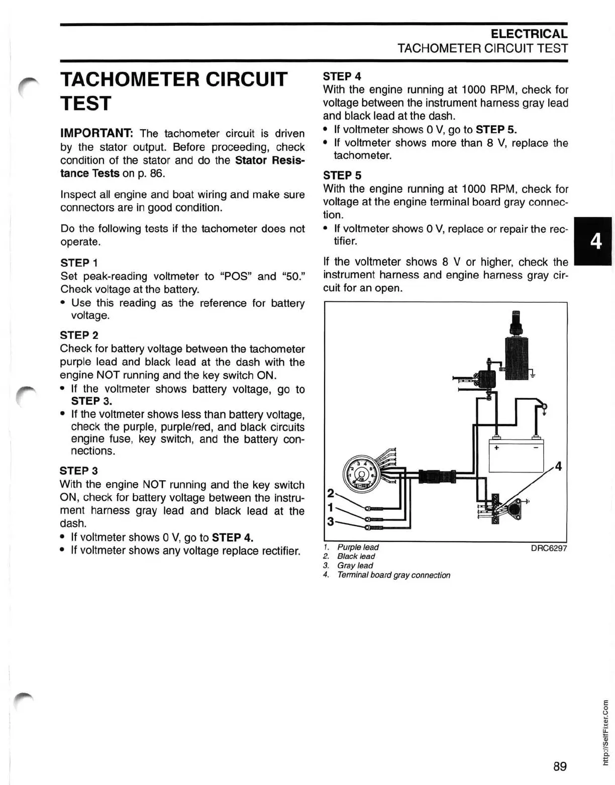
,. Purple lead
2. Black lead
3. Graylead
4. Terminal board gray connection
DRC6297
89
 Loading...