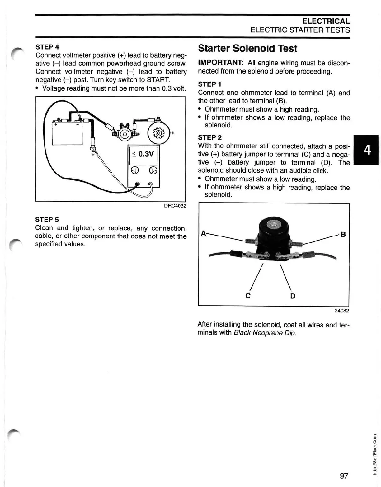
STEP 4
Connect
voltmeter positive (+) lead to battery neg-
ative
(-)
lead common powerhead ground screw.
Connect
voltmeter negative
(-)
lead to battery
negative
(-)
post. Turn key switch to START.
• Voltage
reading must not be more than 0.3 volt.
DRC4032
STEPS
Clean and tighten, or replace, any connection,
cable, or other component that does not meet the
specified
values.
ELECTRICAL
ELECTRIC STARTER TESTS
Starter Solenoid Test
IMPORTANT: All engine wiring must be discon-
nected from the
solenoid before proceeding.
STEP 1
Connect one ohmmeter lead to terminal (A) and
the other
lead to terminal (8).
• Ohmmeter must show a high reading.
• If ohmmeter shows a low reading, replace the
solenoid.
STEP
2
With the ohmmeter still connected, attach a posi-
tive
(+) battery jumper to terminal
(C)
and a nega-
tive
(-)
battery jumper to terminal (D). The
solenoid should close with an audible click.
•
Ohmmeter must show a low reading.
• If ohmmeter shows a high reading, replace the
solenoid.
A
____
______B
/ \
C
D
24082
After installing the solenoid, coat all wires and ter-
minals with Black Neoprene Dip.
97
E
o
U
Qj
)(
~
Qj
~
ii
E
 Loading...