IGNITION
IGNITION SYSTEM TESTS
STEP 3
IMPORTANT: All ohmmeter tests must
be
per-
formed with the engine
NOT running.
Insert jumper wires
in
ignition plate connector, ter-
minals "8" and "C."
DR4622
Calibrate ohmmeter
on
appropriate scale. Con-
nect between jumpers.
• Meter must show 40 ± 10 ohms.
To
test for a grounded condition, connect ohmme-
ter, alternately, between each jumper and a clean
engine ground.
• Any needle movement indicates sensor coil or
leads are grounded.
• Locate and repair ground, or replace sensor
coil.
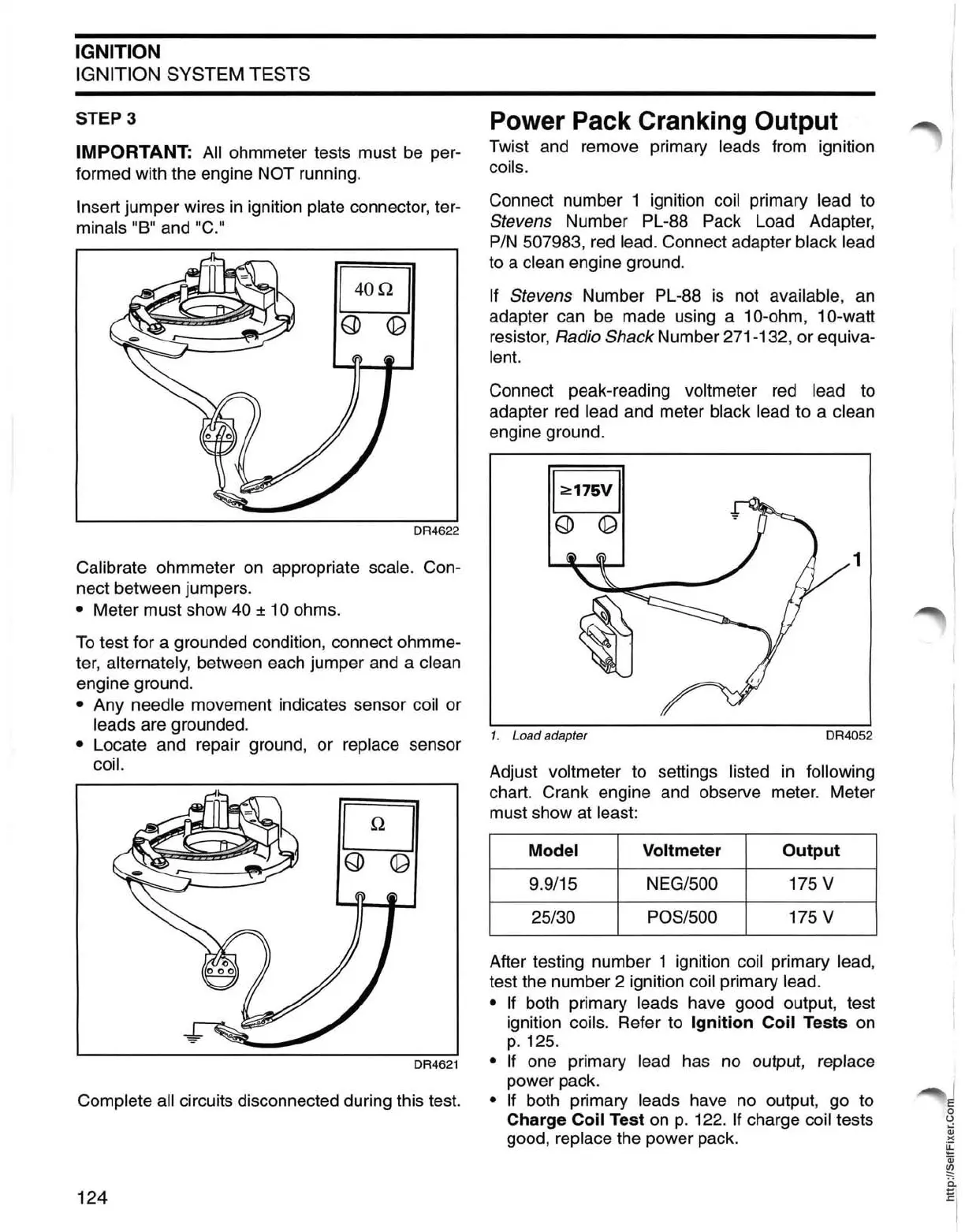
Power Pack Cranking Output
Twist and remove primary leads from ignition
coils.
Connect number 1 ignition
coil primary lead to
Stevens Number PL-88 Pack Load Adapter,
PIN
507983,
red
lead. Connect adapter black lead
to a clean engine ground.
If Stevens Number PL-88
is
not available,
an
adapter can
be
made using a 10-ohm, 10-watt
resistor,
Radio
Shack
Number 271-132, or equiva-
lent.
Connect peak-reading voltmeter red lead to
adapter
red
lead and meter black lead to a clean
engine ground.
1
1. Load adapter DR4052
Adjust voltmeter to settings listed
in
following
chart. Crank engine and observe meter. Meter
must show at least:
Model Voltmeter
Output
9.9/15 NEG/500 175 V
25/30
POS/500 175 V
After testing number 1 ignition coil primary lead,
test the number 2 ignition coil primary lead.
• If
both primary leads have good output, test
ignition coils. Refer to
Ignition
Coil
Tests on
p.125.
DR4621 • If one primary lead has no output, replace
power pack.
Complete all circuits disconnected during this test. • If both primary leads have no output, go to
124
Charge Coil Test
on
p.
122. If charge coil tests
good,
replace the power pack.
 Loading...