– 3 –
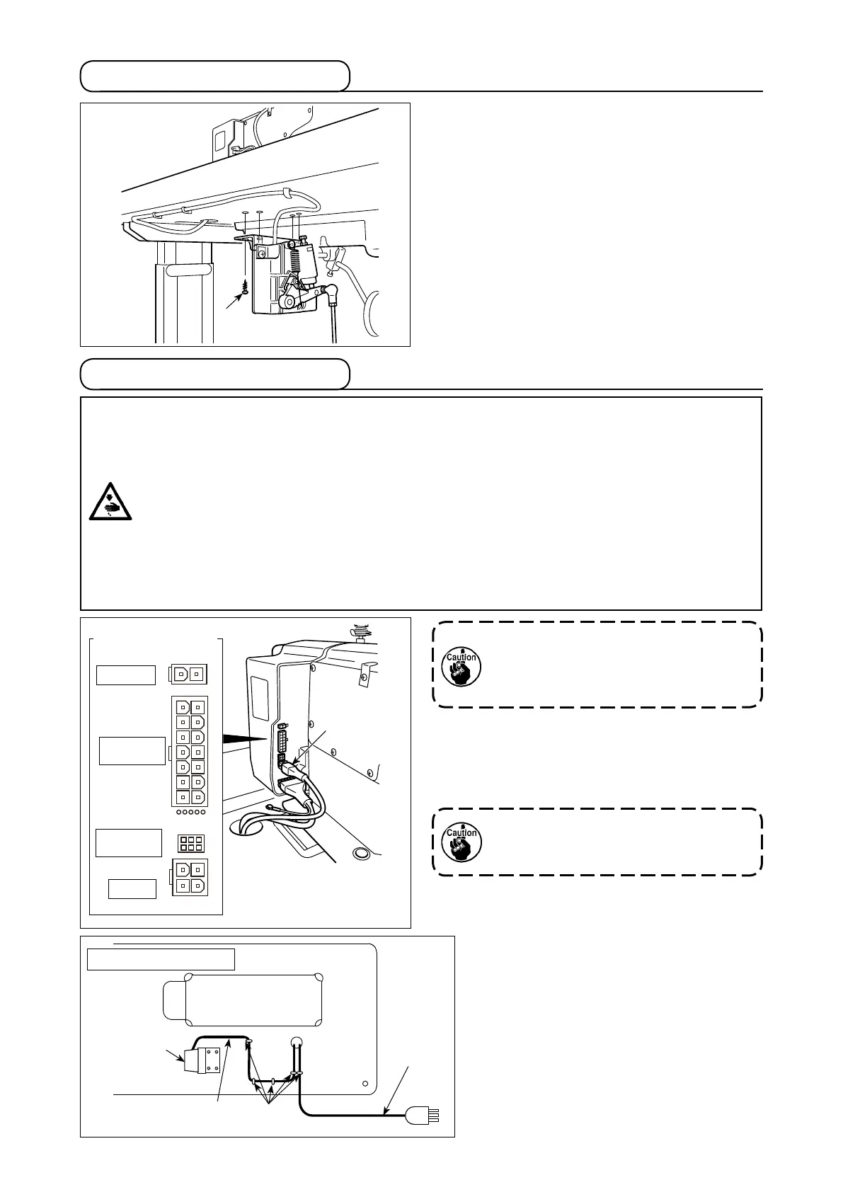
1) Install the pedal sensor to the table with mounting
screws
supplied with the unit.
It is necessary to install the pedal sensor at such
a position that the connecting rod is perpendicular
to the table.
2) After the completion of installation of the pedal
sensor on the table, place the sewing machine
head on the table.
2. Installing the pedal sensor
WARNING :
• To protect against personal injury resulting from abrupt start of the sewing machine, be sure to turn
the power OFF, unplug the machine and wait for ve minutes or more before installing the pedal
sensor.
• To prevent damage of device caused by maloperation and wrong specications, be sure to connect
all the corresponding connectors to the specied places. (If any of the connectors is inserted into a
wrong connector, not only the device corresponding to the connector can break but also it can start
abruptly, inviting the risk of personal injury.)
• To prevent personal injury caused by maloperation, be sure to lock the connector with lock.
• Do not connect the power plug until the connection of cords is completed.
• Fix the cords while taking care not to forcibly bend them or excessively clamp them with staples.
• As for the details of handling respective devices, read carefully the Instruction Manuals supplied
with the devices before handling the devices.
ペペペ
For upgrading
3. Connecting the connector
Connector
connection diagram
Auto-lifter
Solenoid &
LED/TB unit
Pedal
Do not insert the power plug into the
wall outlet.
Check to be sure that the power switch
is turned OFF.
1) Connect pedal sensor cable
supplied with the
unit to the control box.
Refer to the connector connection diagram for
connecting ports of the cables.
Be sure to fully insert the connectors
into the corresponding ports until they
are locked.
2) Fix the pedal cable and AC input cable
with a staple.
Underside of the table
AC cable
Pedal sensor cable
Staples
Pedal sensor
 Loading...