6
1
2
5
4
3
6
7
1
1
2
3
3
6
9
B
7
8
3
4
5
A
2
3
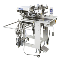
4-5. Installing the electrical box
Install the electrical box on the underside of the table
at the location illustrated using round-head bolt 1, plain
washer 2, spring washer 3 and nut 4 supplied with
the machine, and using bolt having hexagonal
indentation on the head 5, plain washer 6 and spring
washer 7 supplied with the machine.
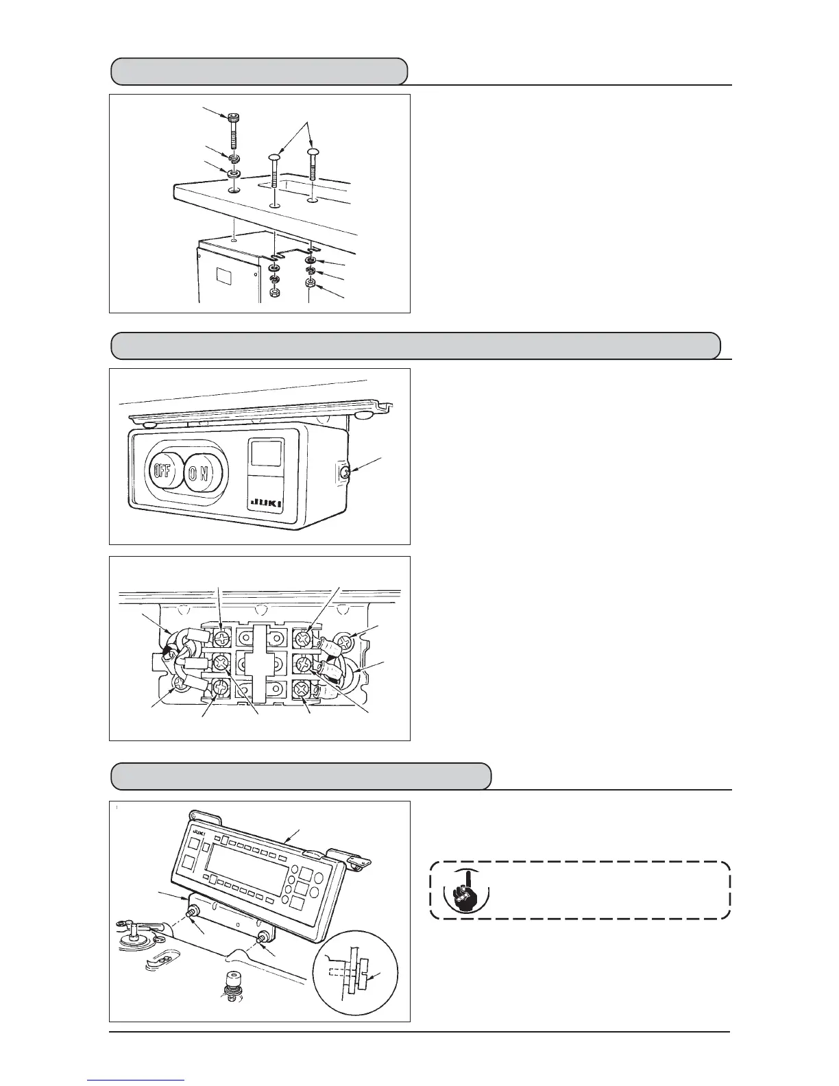
4-7. Installing the operation panel (IP-100)
1) Install operation panel 1 on the machine head using
screws 3 which have been assembled to panel
installing bracket 2.
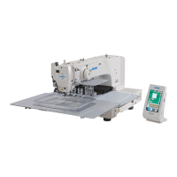
4-6.
Connecting the power switch cord (Japan and general export area)
1) Loosen screw 1 located on the side of the power
switch supplied as accessories and remove the
power switch cover.
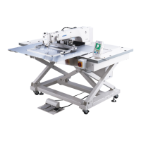
2) Connecting the input power cord of electrical box
¡
When the input power cord of electrical box is 4P
Put 4P cord from hole A of the power switch and
securely fix green/yellow cord to 5, white cord to
2, black cord to 3 and red cord to 4 with screws.
¡
When the input power cord of electrical box is 3P
Put 3P cord from hole A of the power switch and
securely fix green/yellow cord to 5, brown cord to
2 and sky blue cord to 3 with screws.
3)
Connecting the power cable supplied as accessories
¡In case of 3-phase power cable
Put power cable from hole B of the power switch,
and securely fix green/yellow cord to 9, white cord
to 6, black cord to 7 and red cord to 8 with screws.
¡In case of single phase power cable
Put power cable from hole B of the power switch,
and securely fix green/yellow cord to 9 and other
cords to 6 and 7 with screws. 8 is not used.
4) Installing the power switch cover
Securely tighten screw 1 located on the side of
the power switch.
Do not disassemble the operation
panel to prevent it from breakage.
Cau tion
 Loading...