EasyManuals Logo
Home>JUKI>Industrial Equipment>KE-2010

JUKI KE-2010 User Manual

JUKI KE-2010
52 pages
To Next Page IconTo Next Page
To Previous Page IconTo Previous Page
Page #42 background imageLoading...
Page #42 background image
KE2000 Installation Manual
39
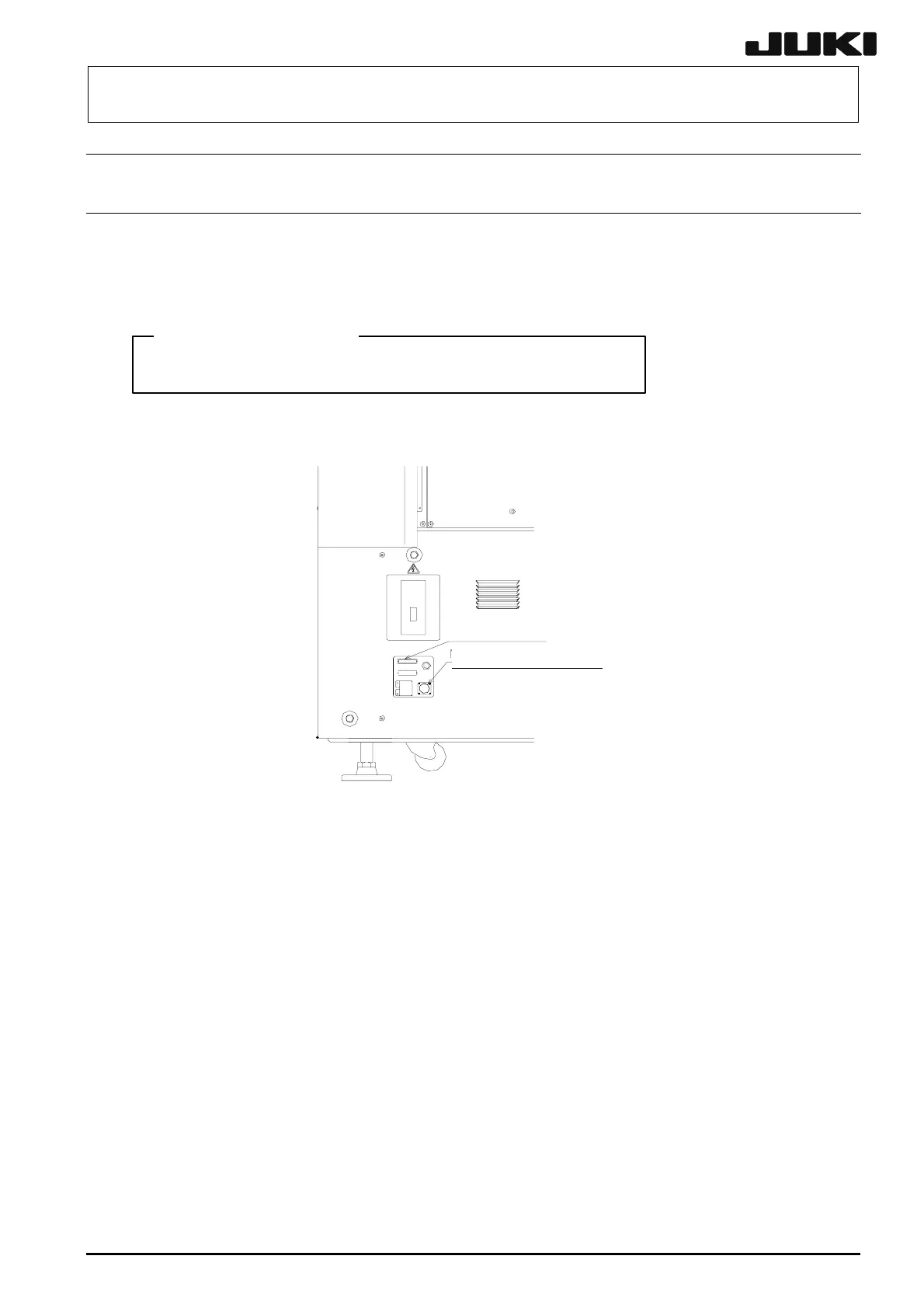
14. Connecting the matrix tray changer (MTC)
14-1. Interface panel
Connect the MTC power connector and signal connector to the interface panel on the
right side of the main unit. Additionally, connect the air tube to the MTC air joint on the
rear of the main unit. (In case of an MTS, connect it on the left side of the main unit.)
<CAUTION>
Always use the cables and air tubes supplied with the MTC.
Fig 14-1-1 Right side view of the main unit
MTC si
g
nal connector
MTC
p
ower connector

Table of Contents

Questions and Answers:

Question and Answer IconNeed help?

Do you have a question about the JUKI KE-2010 and is the answer not in the manual?

JUKI KE-2010 Specifications

General IconGeneral
BrandJUKI
ModelKE-2010
CategoryIndustrial Equipment
LanguageEnglish

Related product manuals