− 7 −
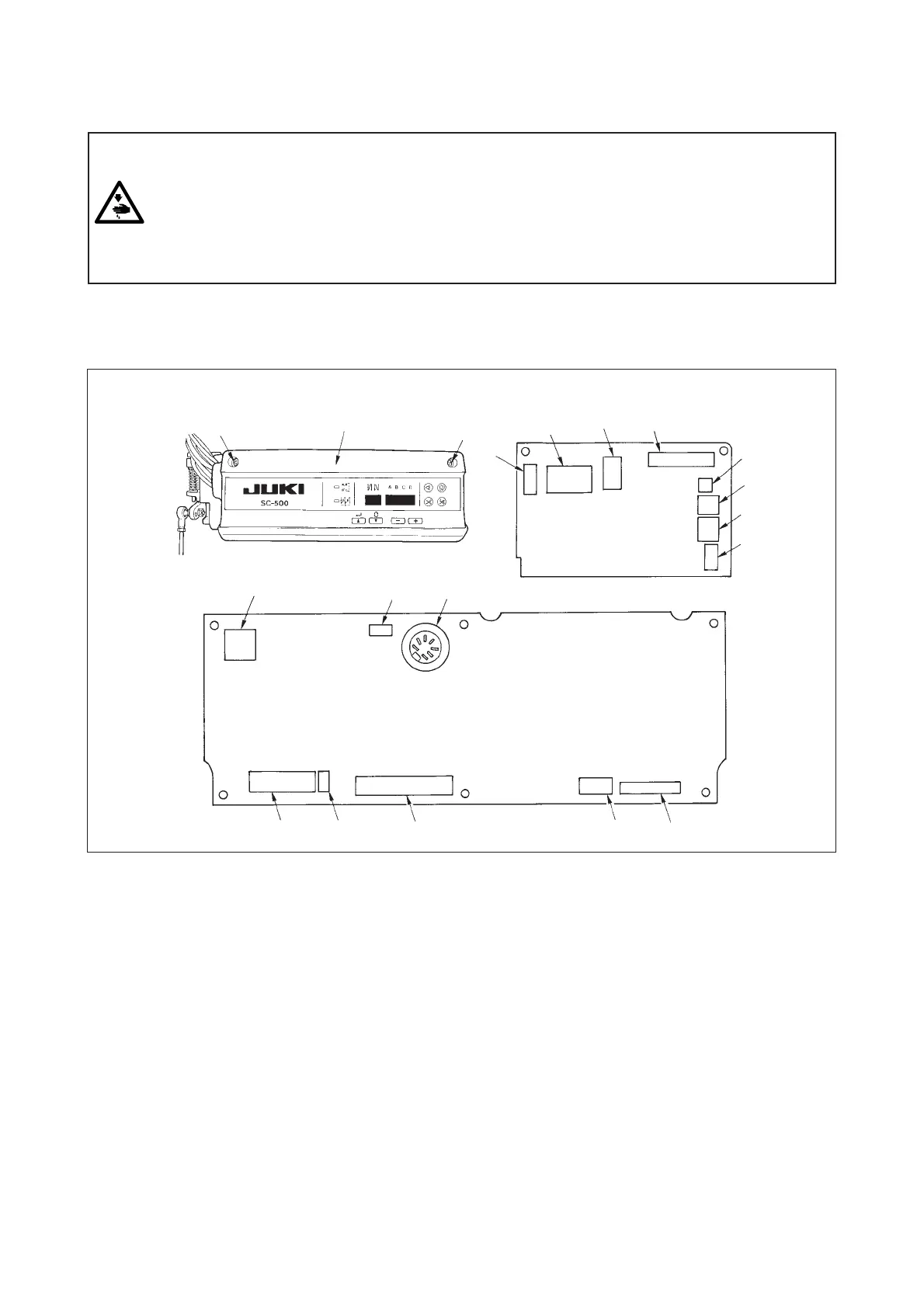
Following connectors are prepared when loosening the front cover fixing screws A of SC-500 and opening the
cover. Connect the machine head connectors to the positions corresponding to each other so as to fit the
devices mounted on the machine head.
WARNING :
• To prevent personal injury caused by abrupt start of the sewing machine, carry out the work after
turning OFF the power switch and a lapse of 5 minutes or more.
• To prevent damage of device caused by maloperation and wrong specifications, be sure to connect
all the corresponding connectors to the specified places.
• To prevent personal injury caused by maloperation, be sure to lock the connector with lock.
• As for the details of handling respective devices, read carefully the Instruction Manuals supplied
with the devices before handling the devices.
(1) Arrangement of connectors
A
9
2
3
1
4
5
!0
7
!2
OPC circuit board A (asm.)
!3
A
Front cover
6
8
!1
!4
!5
!6
1 CN30 Motor signal connector
2 CN32 Machine head connector
3 CN33 Needle bar position detector connector
4 CN36 Machine head solenoid connector
5 CN37 Presser foot lifter solenoid connector
6 CN38 CP-160 panel connector
7 CN39 Standing machine pedal connector
8 CN40 Signal for extension connector
9 CN51 Not used
!0 CN52 Not used
!1 CN53 Bobbin thread remaining amount detection solenoid connector
!2 CN189 External interface signal connector
!3 CN59 Bobbin thread count-up output connector
!4 CN55 Material end detection sensor (ED) connector
!5 CN58 Standing machine pedal connector
!6 CN57 Bobbin thread remaining amount detection sensor connector
6. CONTROL BOX (SC-500)
 Loading...