– 29 –
ENGLISH
I
n addition, there are the following error codes in this device. These error codes interlock (or limit function) and inform the problem so
that the problem is not enlarged when any problem is discovered. When you request our service, please conrm the error codes.
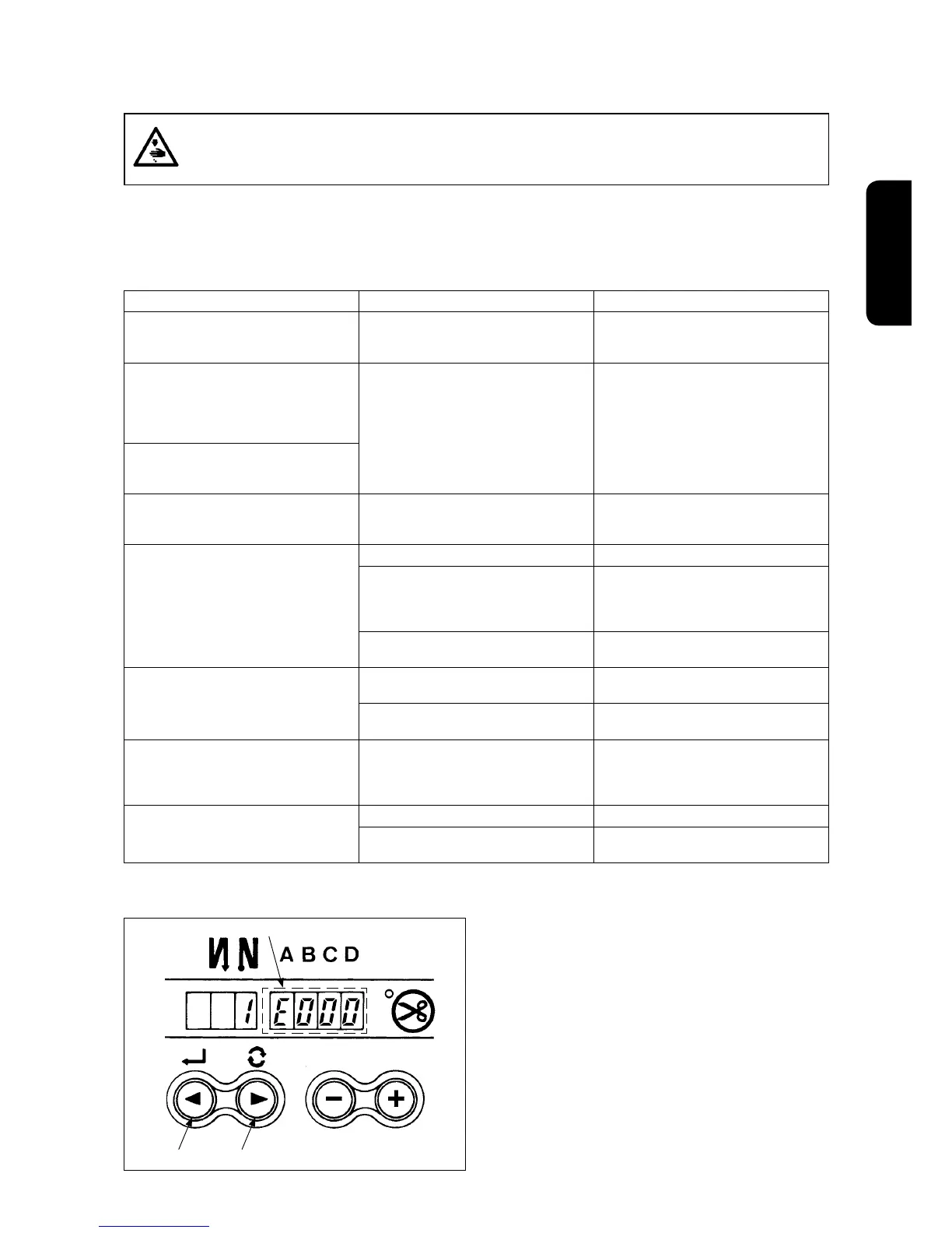
Checking procedure of the error code
1) Pressing switch
1
in the control box, turn ON the
power switch.
2) LED becomes display
5
with the sound of “peep”
and the latest error code is displayed.
3) Confirmation of the contents of previous error
can be performed by operating switches
1
or
2
.
(Caution) When operating switch
1
, one before
the existing error code is displayed.
When operating switch
2
, one after the
existing error code is displayed.
2. Error codes
In case of the following, check again before you judge the case as trouble.
WARNING :
To prevent personal injuries caused by electric shock hazards or abrupt start of the sewing machine,
removethecoverafterturningOFFthepowerswitchandalapseof5minutesormore,andconrm
the trouble to manage.
Phenomenon Cause Corrective measure
Solenoids for thread trimming, reverse feed,
wiper, etc. fail to work. Hand lamp does not
light up.
When the fuse for solenoid power protection
has blown out
Check the fuse for solenoid power protection.
Even when depressing the pedal immedi
-
ately after turning ON the power, the sewing
machine does not run. When depressing the
pedal after depressing the back part of pedal
once, the sewing machine runs.
Neutral position of the pedal has varied.
(Neutral position may be shifted when chang-
ing spring pressure of the pedal or the like.)
Execute the automatic neutral correction
function of the pedal sensor.
The sewing machine does not stop even
when the pedal is returned to its neutral
position.
Stop position of the sewing machine varies
(irregular).
When tightening the screw in the handwheel
is forgotten at the time of adjustment of nee
-
dle stop position.
Securely tighten the screw in the handwheel.
Presser foot does not go up even when
auto-lifter device is attached.
Auto-lifter function is OFF.
Select “FL ON S” by auto-lifter function selection.
Pedal system is set to KFL system. When lifting the presser foot by depressing
the back part of pedal, change the setting to
PFL setting. (For the setting procedure, refer
to the Engineer’s Manual.)
Cord of auto-lifter device is not connected to
connector (CN37).
Connect the cord properly.
Touch-back switch fails to work. Presser foot is going up by auto-liter device. Operate the switch after the presser foot
lowered.
Auto-lifter device is not attached. However,
auto-lifter function is ON.
Select “FL OFF” when auto-lifter device is not
attached.
UP position move fails to work when all
lamps on the panel light up.
The mode is in the function setting mode.
The switch on the CTL p.c.b. is pressed by
the bound cords and the aforementioned
mode resulted.
Remove the front cover, and arrange the
cords by the regular binding procedure de-
scribed in the Instruction Manual.
Sewing machine fails to run. Motor output cord (4P) is disconnected.
Connect the cord properly.
Connector (CN30) of motor signal cord is
disconnected.
Connect the cord properly.
* This device is designed so that "system-down" occurs to protect the breakdown of electrical components
when high-voltage such as thunders, etc. is applied for a short time.
At this time, the indication goes out and the sewing machine does not operate.
<Corrective measure>
Turn OFF the power switch, remove the cause and turn ON the power switch after the red LED inside the
control box that can be seen from the power connector section has gone out.
2
1
5
 Loading...