– 9 –
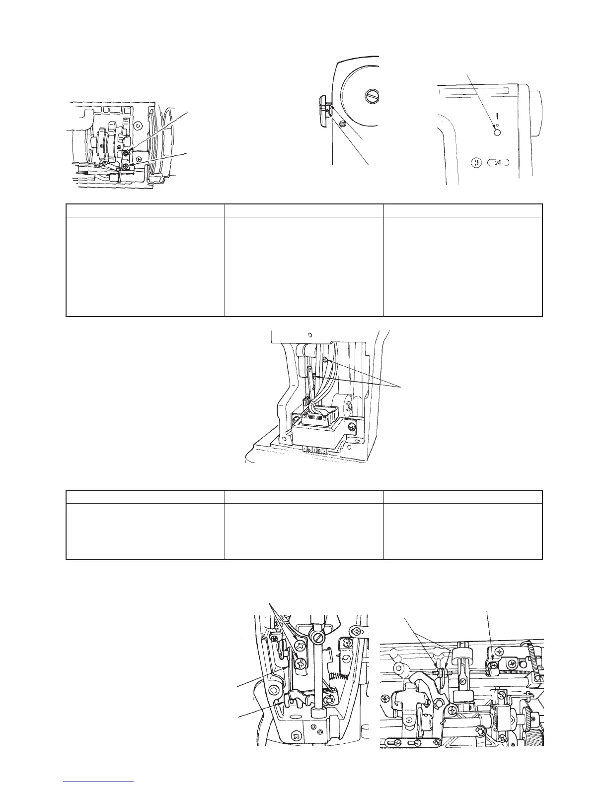
9. Stitch dial
Preparation
™ Remove arm cover asm.
10.Thread trimming switch case
Preparation
™ Remove arm cover asm.
™ Remove motor cover and belt cover.
™ Remove motor mas. asm.
1 Thread trimming switch
circuit board case setscrew
SL4040655SN
11.Wire holder
Preparation
™ Remove outer components.
(Excluding belt cover and motor cover)
™ Remove presser bar.
1 Nut of setscrew
(opposite side 9 mm)
NS6620310SP
2 Wire tube presser
setscrew
SM4040655SN
3 Feed regulating screw
stopper asm. setscrew
5 Feed regulating screw
• Stopper screw
• Stopper nut
Disassembly
Loosen two setscrews of 1 and
remove the dial.
Be careful since pin of 2 jumps.
3 may not be removed.
(Stopper screw SM8031400TP)
Assembly
™ Turn regulating screw 4 full to the
right.
™ Assemble stitch dial with its scale
0 up and tighten screw 1 (2 pcs.).
Point
™ There should be no play in feed
regulator when operating lever.
(When scale is 0.)
™ Loosen stopper nut of 5. Make
stopper screw strike against
regulating screw 4 and tighten
nut.
2 Feed regulating
pin
1 Stitch dial setscrew
SM8030402TP
4 Feed regulating screw
Disassembly
Remove two setscrews in 1 thread
trimming switch case.
™ Remove thread trimming switch
case.
Assembly
™ Attach the switch case to frame
and tighten with setscrews 1.
Point
™ There should not be no torsion
between switch and frame.
3 Wire holder setscrew
SM5040855SN
5 Disk pressure release
connecting link
4 Thread release plate
 Loading...