– 5 –
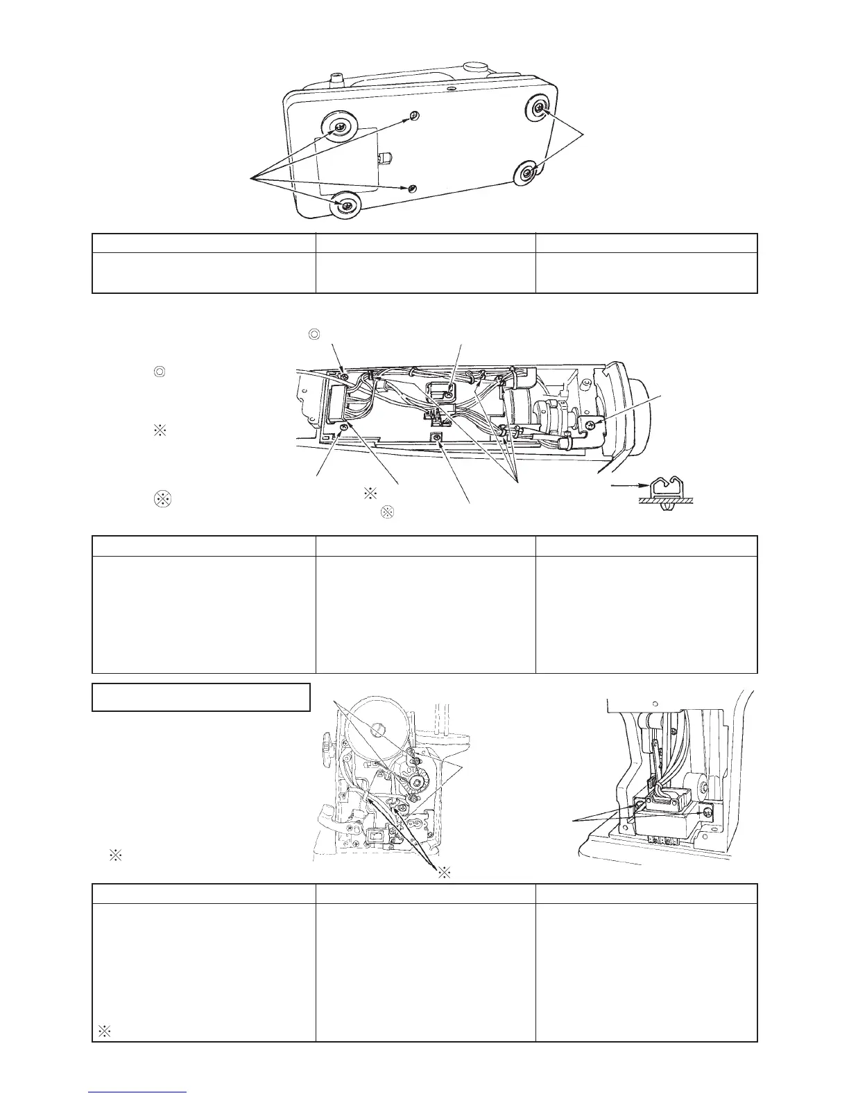
5. MAIN circuit board asm.
Preparation
™ Remove arm cover asm.
Note) Setscrew to set the
circuit board and cover
to circuit board case
Do not insert in the
reverse direction.
(See page 15.)
Do not loosen
this screw.
4. Bed cover mas. asm.
1. Motor asm. and
transformer asm.
Preparation
™ Remove arm cover asm.
™ Remove belt cover and
motor cover respectively.
Make a memorandum of
cord wiring.
PointDisassembly
Remove six setscrews of 1 and
remove bed cover.
Assembly
™ Attach bed cover and tighten
setscrews.
1 Bed cover setscrew
SM5051255SN
1 Bed cover setscrew
Point
™ Read the note and understand it.
™ Ther are color indications on the
circuit board for inserting
connectors.
Disassembly
™ Remove 10 connectors of each
lead wire.
Remove lead wire from mini-clamp of
1.
Remove setscrews of 2 and 4, and
remove circuit board.
Assembly
Attach circuit board and tighten
setscrews.
™ Insert each lead wire into
connectors.
3 MAIN circuit board
setscrew
4 MAIN circuit
board case
setscrew B
SM5031401SE
Porality exists.
Never loosen this screw.
2 MAIN circuit board case setscrew A
SL5030831SF
5 Cord guide
plate setscrew
SM5030655SN
1 Mini-clamp
(4 places)
Cord guide
plate asm.
Point
™ Loosen nuts of 3 to adjust motor
tension.
™ Belt tension : the belt should sag
3 to 4 mm when center of belt is
applied with 1.96N load.
Disassembly
™ Cut clip band of 5 cord guide
plate asm. in previous item.
Remove two setscrews of 1 and
remove motor asm.
Remove two setscrews of 2 and
remove transformer asm.
Make sure of wiring route.
Assembly
™ Attach transformer and tighten
setscrews.
™ Attach motor asm. and tighten
setscrews.
™ Attach cord guide plate asm. and
tighten setscrew.
Function Components
2 Power transformer
setscrew
SM5040855SN
3 Motor setscrew nut
1 Motor asm.setscrew
SM5050855SN
Position of cable
 Loading...