– 6 –
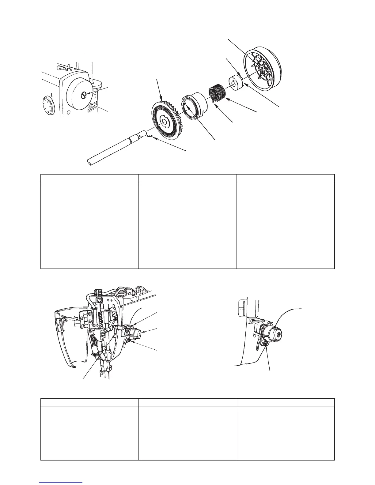
2. Handwheel and clutch
Preparation
™ Remove belt cover.
3. Thread tensioner asm.
Disassembly
Remove setscrew of 1.
Remove cord guide plate setscrew
and remove cord guide plate asm.
Remove spring support of 3.
Move 4 in the direction where clutch
spring is released and remove clutch
spring.
Face 6 to motor side and 8 is hard
to drop.
Draw out 8 and remove 9.
Assembly
Attach 9 and enter 8.
™ Enter groove 6 of bushing to
stopper pin 8 and attach bushing.
™ Enter hook portion 5 of spring to
slit in the center of handwheel
bushing
™ Enter clutch spring 5 to groove
3 of spring support and attach
cord guide plate asm. Then
tighten setscrew.
Point
™ Align convex 7 of bushing with
groove !0 of handwheel and
attach handwheel. Then tighten
setscrew.
Clearance provided between convex
of clutch spring support 3 and clutch
plate is 2 ± 0.5 mm.
See item 12 on page 19 for adjustment.
1 Handwheel
setscrew
2 Handwheel
9 Motor pulley
6 Groove of handwheel
bushing
8 Handwheel bushing stopper pin
4 Angle portion of clutch spring
7 Convex of handwheel bushing
5 Hook portion of clutch spring
3 Groove of clutch spring support
!0 Groove of handwheel
Disassembly
Remove setscrew of 1.
™ Lower presser foot and remove
setscrew of 2.
Remove spring of 3 together with
thread tensioner asm. of 4 and
adjusting plate.
Assembly
™ Attach adjusting plate and spring
3 to thread tensioner asm. and
attach it to frame. Then fix it with
setscrew of 2.
™ Tighten adjusting plate setscrew
1.
Point
™ Place upward the scale of thread
tension disk presser 5.
™ See items 9 and 10 on page 18
for adjustment of pressure and
stroke of thread take-up spring.
1 Thread take-up spring
adjusting plate setscrew
SL5030801SN
2 Thread tensioner setscrew
SM8040602TP
3 Thread take-up spring
4 Thread tensioner asm.
5 Thread tension disk presser
 Loading...