–
17
–
General mechanism
1. Height of neddle bar bushing ........................... 18
2. Height of needle bar ......................................... 18
3. Height of presser foot ....................................... 18
4. Height of feed dog ............................................ 19
5. Feed timing ....................................................... 19
6. Needle-to-hook timing ...................................... 19
7. Clearance between needle and hook ............... 19
8. Position of bobbin case positioning nger ........ 20
9. Stroke of thread take-up spring
(absorbing amount of thread) ........................... 20
10. Tension of thread take-up spring ........................ 20
11. Bobbin thread tension ...................................... 21
12. Position of bobbin winder clutch ....................... 21
13. Adjustment of bobbin winder ............................ 22
14. Position of threader support plate mas. asm. ... 23
15. Vertical position of threader hook ..................... 23
Automatic thread trimmer mechanism
1. Positioning of moving knife arm installing plate
(adjustment of position of moving knife) ........... 24
2. Installing position of thread trimmer solenoid
(moving amount of thread trimmer cam
contactor shaft) ................................................. 24
3. Thread trimmer cam timing
(needle-to-cam position) ................................... 25
4. Position and protruding amount of looper
(left/right position and adjustment of movement)
......................................................................... 28
5. Position of nut of wire setscrew
(adjustment of thread tension disk open/close)
......................................................................... 28
[5] ADJUSTMENT OF COMPONENTS
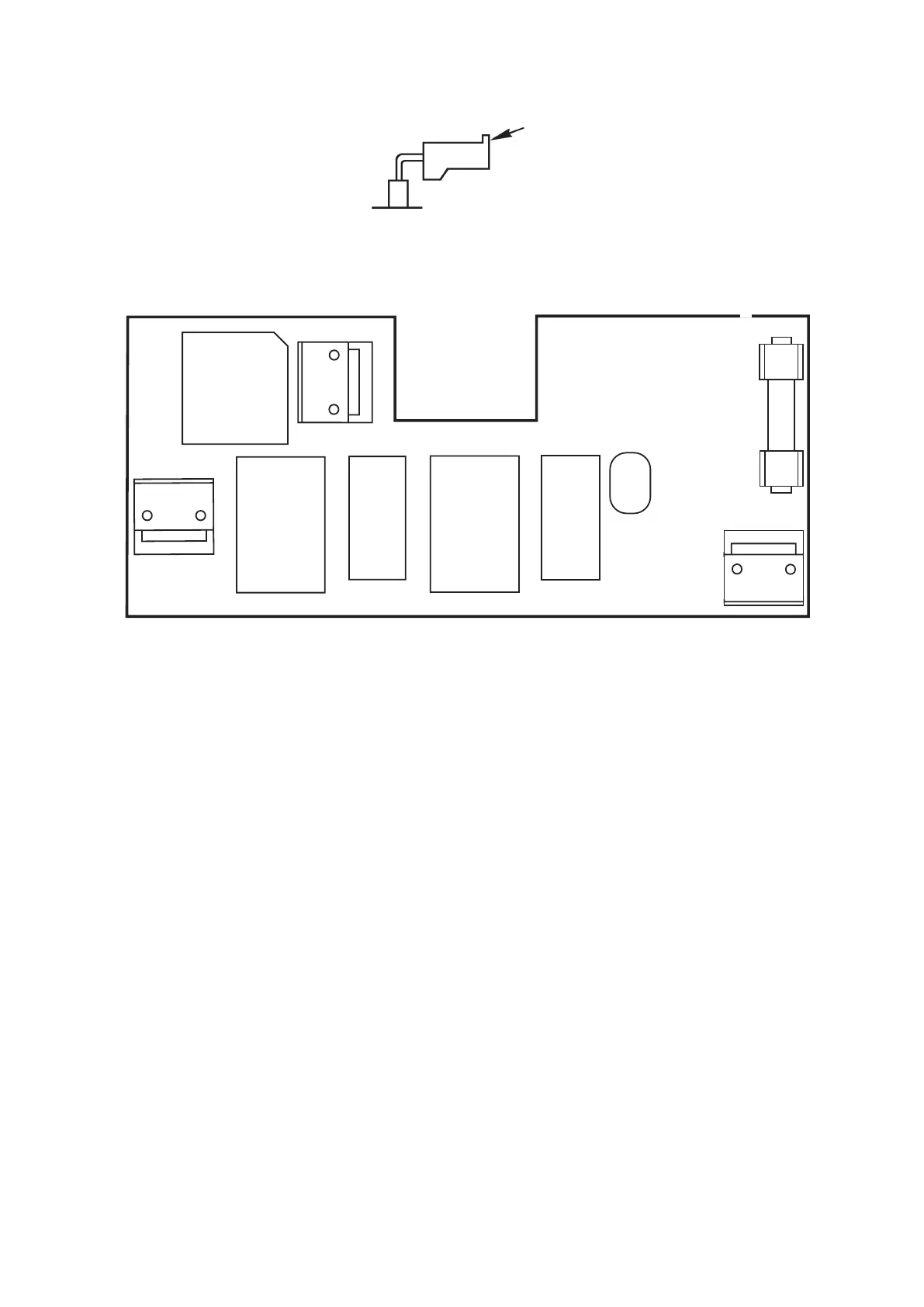
(Caution) Convex portion of connectors, CN7, CN8 and CN9 should be placed up.
Connector insertion diagram
Convex portion
(FILTER circuit board)
CR1
CN22
L1
CN21
C2
WHT
BLU
1
1
1
BRN
C1
L2
CN23
ZNR1
F1
〜
〜
-
-
AC 120V: 5A/125V
AC 220-240V: 3.15A/250V
( )
 Loading...