EX2200-24-4G REV: X1
750-026464 REV: X3
MAC: 00:23:9C:oE:19:00
Mfg. Date
20090227
MADE IN CHINA
g021302
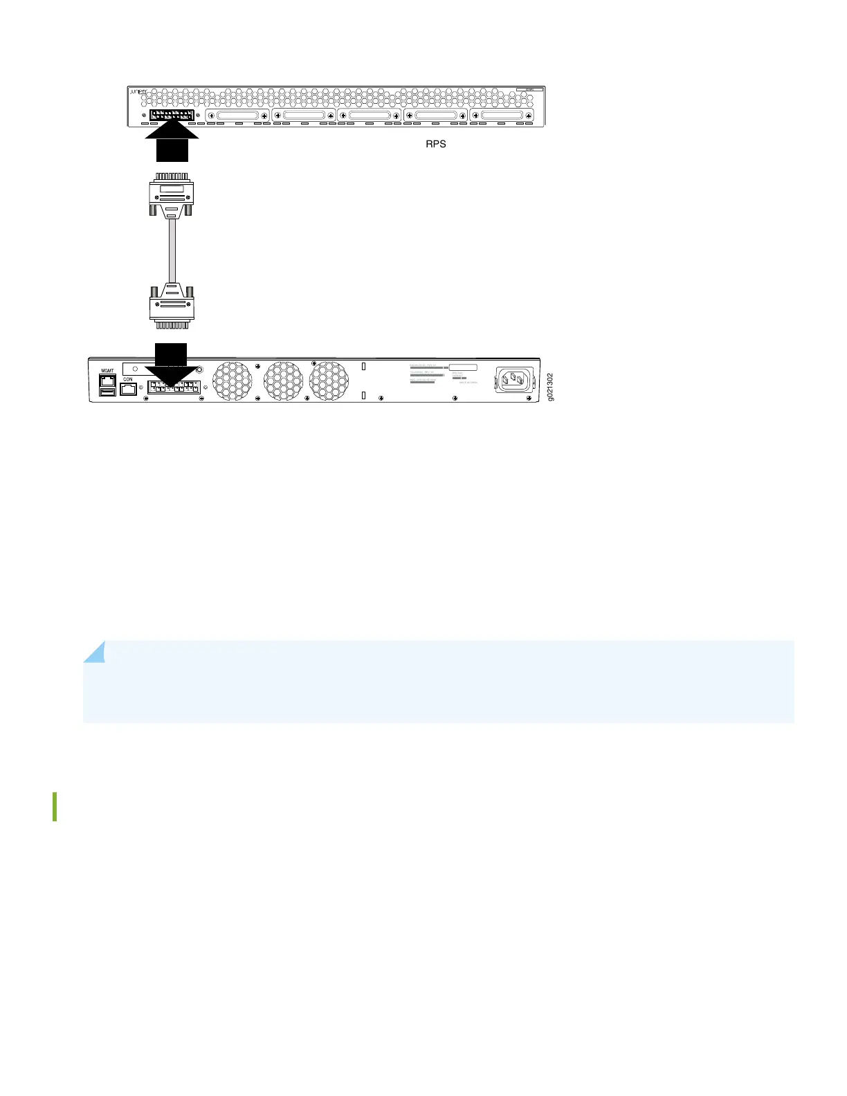
RPS
4. If the RPS connector on the RPS chassis has a cover on it, remove the cover panel.
5. Connect the cable to the uncovered RPS connector. The RPS software starts configuring a connection as soon as both
sides of the cable are connected.
6. After a minute, verify connection status. The Status LED corresponding to the connector should be lit. The LED can
be steady (connected), blinking (supplying power), or off (no connection).
7. Connect up to five more switches.
NOTE: You can also determine connection status by issuing the show redundant-power-system led command
on the switch.
Installation is Complete
Your RPS is now installed and capable of providing either PoE or non-PoE backup power to one attached switch per power
supply. You can check RPS status from any connected switch using the command show chassis redundant-power-supply.
5
 Loading...