trained in its use. You may wish to use a driver that is designed to prevent
overtorque when the preset torque level is achieved.
7. Replace the clear plastic cover over the terminals on the faceplate.
8. Repeat Step 2 through Step 7 for the remaining power supplies.
9. Attach an electrostatic discharge (ESD) grounding strap to your bare wrist, and connect
the strap to an approved site ESD grounding point. See the instructions for your site.
10. Connect each DC power cable to the appropriate external DC power source.
NOTE: For information about connecting to external DC power sources,
see the instructions for your site.
11. Switch on the external circuit breakers to provide voltage to the DC power source
cable leads.
12. Switch on the circuit breakers on each power supply to the on position (|). Observe
the status LED on each power supply faceplate. If a DC power supply is correctly
installed and functioning normally, the status LED lights green steadily.
If the status LED indicates that the power supply is not functioning normally, repeat
the installation and cabling procedures.
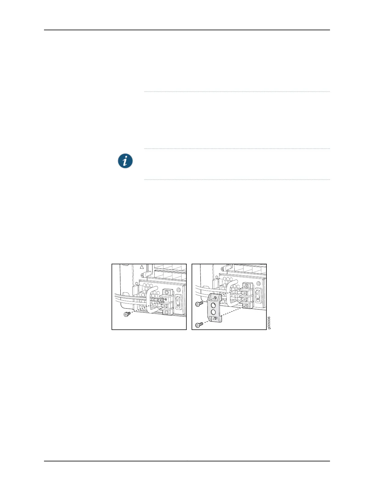
Figure 10: Connecting DC Power to the Router
15Copyright © 2015, Juniper Networks, Inc.
Connect Power to a DC Router

 Loading...