16
2. CONTROLS, INDICATORS AND CONNECTORS
PUSH
LINE OUT
Y/C OUT
CH-1
CH-2
MONITOR OUT
FRONT
AUDIO IN
LENS
ewq
r
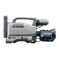
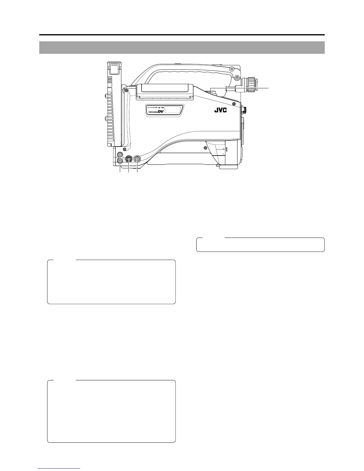
2-3 Left Side Section
1
[MONITOR OUT] Monitor output connector (BNC)
● Composite video signal output connector.
● Video signals with setup level are output.
(Whether or not setup level output should be enabled or
disabled can be selected with the SETUP item on the
AUDIO/VIDEO menu screen.)
Camera mode: The camera image is output.
VTR mode: The playback image is output in the VTR
playback mode. When a DV signal (IEEE1394) is input,
the EE image of the input video signal is output.
MEMO:
● When the OUTPUT CHAR. item on the OTHERS
(1/2) menu screen is set to ON, the same on-screen
indications as those on the viewfinder will be shown
on the external monitor. (Black and white indications)
● The setup signal can be selected also for the EE
output signal of the DV input.
2
[Y/C OUT] Y/C output connector (4-pin)
● Output connector for separate YC video signal.
● Video signals with setup level are output. (Whether or
not setup level output should be enabled or disabled can
be selected with the SETUP item on the AUDIO/VIDEO
menu screen.)
Camera mode: The camera image is output.
VTR mode: The playback image is output in the VTR
playback mode. When a DV signal (IEEE1394) is input,
the EE image of the input video signal is output.
MEMO:
● When the ASPECT RATIO item on the CAMERA
OPERATION menu screen is set to LETTER, 16:9
aspect ratio distinction ID signal is output.
● When the OUTPUT CHAR. item on the OTHERS
(1/2) menu screen is set to ON, the same on-screen
indications as those on the viewfinder will be shown
on the external monitor. (Black and white indications)
● The setup signal can be selected also for the EE
output signal of the DV input.
3
[CH1/CH2 LINE OUT] CH1/CH2 line output
connector (RCA)
Output connector for audio signals.
● Outputs the input audio signal in the Camera mode.
● Outputs the playback audio signal or DV signal in the
VTR mode.
MEMO:
● Alarm sound is not output.
4
Microphone attachment holes
For attaching the microphone holder KA-A50 (optional)
when the optional microphone MV-P615U or MV-P618U is
used.
☞ See “Attaching the Microphone (optional)” on page 31.
 Loading...