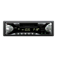
KS-F171
(No.49774)1-17
4.2 LC72362N-9B39 (IC701) : Micon
•Pin layout
• Pin functions
41 - 64
24 - 1
25
40
80
64
-
-
Pin
No.
Symbol I/O Function
1 XIN I Crystal oscillator
2GND-To GND
3 J BUS SI I Bus serial data input from CP751
4 J BUS SO O Bus serial data output to CP751
5 J BUS SCK O Bus serial clock output to CP751
6 J BUS I/O SEL O BUS I/O switch signal output
7 NC - Non connect
8 LCD SO O Serial data output to IC651
9 LCD SCK O Serial clock output to IC651
10 LCD CE O Chip enable output to IC651
11 NC - Non connect
12 E.VOL SO O Serial data output
13 E.VOL SCK O Serial clock output
14 CE - Chip enable output
15 TUNER ILLUM - Non connect
16 TAPE ILLUM - Non connect
17 CD ILLUM - Non connect
18 DIMMEROUT - Non connect
19 NC - Non connect
20 NC - Non connect
21 NC - Non connect
22 NC - Non connect
23 NC - Non connect
24 NC - Non connect
25 KS1 - Non connect
26 KS0 O Initializing output port
27 K3 I Initializing input port
28 K2 I Initializing input port
29 K1 - Non connect
30 K0 I Initializing input port
31 Vdd - Power supply
32 TEST I Test iput
33 NC - Non connect
34 SEEK/STOP O Output the "If signal request"
35 MONO O Monaural and stereo change over
output
36 R/T - Non connect
37 NC - Non connect
38 POWER CNT O Power control output
39 NC - Non connect
40 NC - Non connect
41 IF CONT - Non connect
42 NC - Non connect
43 NC - Non connect
44 NC - Non connect
45 NC - Non connect
46 NC - Non connect
47 NC - Non connect
48 TAPE IN I H:RADIO L:TAPE
49 F/R SENCE I FORWARD/REVERSE switch de-
tector
50 TAPE MUTE I DIR.FF/REW.MUTE
51 SD/ST I Station detector and ST input
52 NC - Non connect
53 DETACH I Detection of Front Panel
54 NC - Non connect
55 J BUS INT I BUS interruption signal detection
communication
56 REMOCON - TO GND
57 FM/AM I Change over the FM/AM iuput
58 DOLBY - Non connect
59 NC - Non connect
60 MUTE - The mute time is controlled by the
connected
61 MEMORY DET I Memory detector input
62 LEVEL METER I -----
63 SMETER I Signal meter input
64 KEY 2 I Momentary key input
65 KEY 1 I Momentary key input
66 KEY 0 I Momentary key input
67 ACCDET I ACC DET
68 SENS - To GND
69 NC I Non connect
70 FM/AM IF COUNT - AM/FM Frequency detection
71 NC - Non connect
72 NC - Non connect
73 Vdd I Power supply
74 AM OSC I Input the local oscillator signal of
AM
75 FM OSC - Input the local oscillator signal of
FM
76 Vss - Power supply
77 NC - Non connect
78 EO - PLL Error signal output
79 TEST 1 O To GND
80 XOUT O Crystal oscillator
Pin
No.
Symbol I/O Function

 Loading...