KS-F171
1-22 (No.49774)
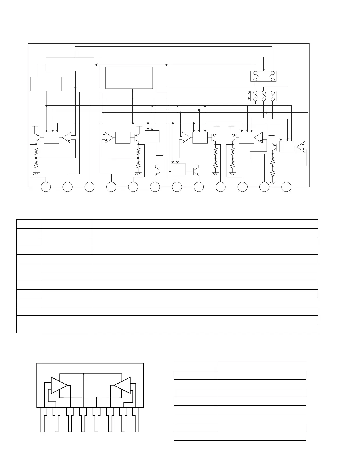
4.5 AN80T05LF (IC781) : Regulator
• Pin layout & Block diagram
• Pin function
4.6 UPC1228HA (IC901) : Head amp
• Pin layout & Block diagram • Pin function
Pin No. Symbol Function
1 ILL 10V power supply for illumination.
2 MODE2 When 5V is input,becomes AM. and the antenna output is turned on.
3 MODE1 When 5V is input,becomes AM. and the output of FM is switched.
4 STB When 5V is input outputs to ILL,COM and AMP. It is 0V usually.
5 VDD 5.6V power supply.
6 AMP Power supply supply to remote amplifier
7 VCC Back up. connects with ACC with it.
8 ANT Power supply supply to auto antenna.
9 COM 8.7V power supply.
10 AM The power supply of 8.7V to AM.
11 FM The power supply of 8.7V to FM.
12 GND Ground
Pre
Drive
Thermal
Protection
Reference Voltage
Pre
Drive
AMP
Out
ASO & Peak
Current Protection
AMP
Out
Pre
Drive
Pre
Drive
Pre
Drive
123456789101112
ILL
10V
MODE2 MODE1 STB VDD
5.6V
AMP VCC ANT COM
8.7V
AM
8.7V
FM
8.7V
GND
1
AMP1 AMP2
2345678
Pin No. Symbol
1 Input 1
2 Negatice feed back 1
3 Output 1
4 Power supply; +Vcc
5 Ground
6 Output 2
7 Negative feed back 2
8 Input 2
 Loading...