KS-F171
1-8 (No.49774)
2.2 Cassette mechanism assembly
• Prior to performing the following procedures, remove the head
amplifier board, the relay board and the mechanism bracket.
2.2.1 Removing the direction switch board
(See Fig.1)
(1) Unsolder the three wires a on the direction switch board.
(2) Remove the one screw A attaching the direction switch
board.
2.2.2 Removing the FF / REW lever assembly
(See Fig.1)
(1) Remove the screw B attaching the FF / REW lever assem-
bly on the back of the cassette mechanism assembly.
(2) Remove the screw C on the upper side of the FF / REW
lever assembly.
(3) Lift and pull forward the FF / REW lever assembly to disen-
gage the joints b, c, d and e.
2.2.3 Reattaching the FF / REW lever assembly
(See Fig.1)
(1) Reattach the FF / REW lever assembly to the joint c on the
back of the chassis.
(2) Reattach the pinch-roller shaft e, the change lever d and
the return link e to the chassis.
Fig.1
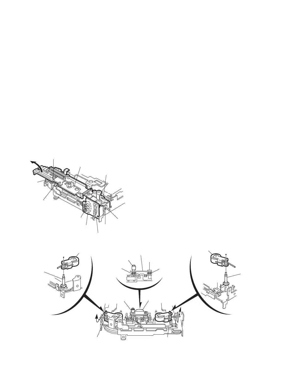
2.2.4 Removing the playback head
(See Fig.2)
• Prior to performing the following procedure, remove the direc-
tion switch board and the FF / REW lever assembly.
(1) Remove the screw D attaching the playback head.
(2) Remove the C washer and pull out the FF roller.
(3) Remove the S support plate, the A arm spring (a) and (b),
the playback head.
ATTENTION:
The A arm spring (a) differs from the A arm spring (b).
2.2.5 Removing the pinch-roller (R) and (F) assembly
(See Fig.2)
• Prior to performing the following procedure, remove the direc-
tion switch board and the FF / REW lever assembly.
(1) Remove the P arm spring (f) in the pinch-roller (F) assem-
bly from the chassis.
(2) Remove the P arm spring (r) in the pinch-roller (R) assem-
bly from the chassis.
(3) Draw out the pinch roller (F) and (R) assembly from the
shaft.
ATTENTION:
The P arm spring (f) differs from the P arm spring (r).
ATTENTION:
The pinch roller (F) assembly differs from the pinch roller (R)
assembly.
Fig.2
C
FF / REW lever assembly
Joint c
Joint b
B
A
Direction switch board
Joint d
Joint e
Soldering a
A arm spring (b)
A arm spring (a)
Pinch-roller (R) assembly
Pinch-roller (F) assembly
Shaft
Shaft
S support plate
D
C washer
P arm spring (f)
P arm spring (r)
Remove the P arm spring (f)
from the chassis.
Remove the P arm spring (r)
from the chassis.
Playback head
FF roller
 Loading...