KS-F171
1-4 (No.49774)
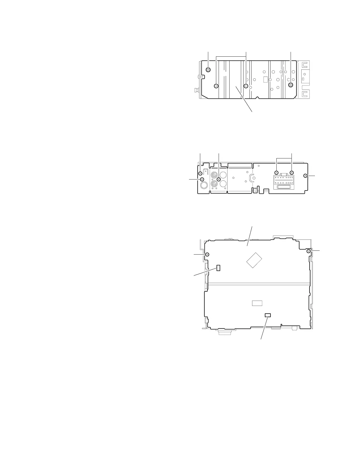
2.1.4 Removing the heat sink
(See Fig.4)
• Prior to performing the following procedure, remove the front
panel assembly.
(1) Remove the two screws B and two screws C attaching the
heat sink on the left side of the body, and remove the heat
sink.
Fig.4
2.1.5 Removing the rear panel
(See Fig.5 )
• Prior to performing the following procedure, remove the front
panel assembly and bottom cover.
(1) Remove the two screws D, one screw E and three screws
F attaching the rear panel on the back of the body.
Fig.5
2.1.6 Removing the main board
(See Fig.6)
• Prior to performing the following procedure, remove the front
panel assembly, bottom cover, front chassis, heat sink and
rear panel.
(1) Remove the two screws G attaching the main board on the
top chassis.
(2) Disconnect the two connectors CN901 and CN721 on the
main board from the cassette mechanism assembly.
Fig.6
Heat sink
CB C
D
FF
E
D
G
G
Main board
CN901
CN721
 Loading...