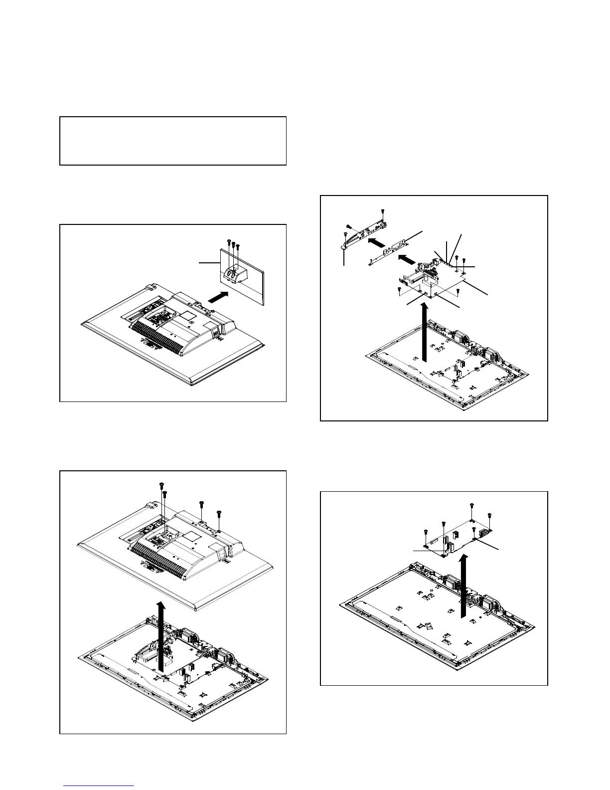
1. REMOVAL OF MECHANICAL PARTS
1-3: MAIN PCB (Refer to Fig. 1-3)
AND P.C. BOARDS
Disconnect the following connectors:
(CN2, CN3, CN5, CN6, CN11 and CN17)
Be careful not to remove the LVDS cable forcibly, because
the LVDS cable may be damaged.
Remove the Plate Jack in the direction of arrow (A).
Remove the Shield Jack in the direction of arrow (B).
1-1: STAND ASS'Y (Refer to Fig. 1-1)
Remove the Main Unit in the direction of arrow (C).
Remove the Stand Ass'y in the direction of arrow.
(1)
(1)
(1)
Stand Ass'y
(1)
(2)
(2)
(A)
Plate Jack
(B)
Shield Jack
(3)
(3)
(3)
(C)
CN11
CN3
(3)
Main Unit
CN2
CN5
CN6
CN17
1-2: BACK CABI ASS'Y (Refer to Fig. 1-2)
1-4: POWER PCB (Refer to Fig. 1-4)
Remove the Back Cabi Ass'y in the direction of arrow.
Disconnect the following connector:
3. Remove the Power PCB in the direction of arrow.
Fig. 1-4
Fig. 1-3
Fig. 1-1
Fig. 1-2
(1)
(2)
(2)
(2)
(1)
(1)
(1)
(1)
(1)
Power PCB
CP7001
 Loading...