1-10 (No.MB412)
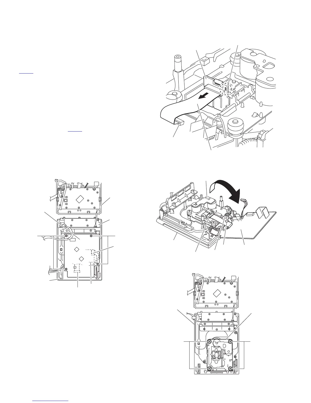
3.1.4 Removing the CD mechanism board, CD mechanism
(See Fig.11 to 14)
• Prior to performing the following procedure, remove the rear
cover assembly, the main board and the CD mechanism as-
sembly.
Caution:
Make sure to solder the short-circuit point on the CD pickup
board before disconnecting the card wire from connector
CN601
on the CD mechanism board and from the CD pickup
board. If you do not follow this instruction, the pickup may be
damaged.
(1) Remove the four screws J on the CD mechanism assem-
bly.
(2) Disconnect the wire from connector of the CD motor board.
(3) Solder the short-circuit point on the CD pickup board, and
disconnect the wire from the CD pickup board.
Caution:
To reattach the CD mechanism board, connect the card
wire to connector CN601
on the CD mechanism board
and to the CD pickup board, then unsolder the short-cir-
cuit point.
(4) Remove the screw K attaching the wire on the CD mecha-
nism board.
Caution:
The metal washer and nut come off.
(5) Remove the four screws L attaching the CD mechanism.
Fig.11
Fig.12
Fig.13
Fig.14
JJ
Switch board
CD mechanism
board
CD mechanism
assembly
Front panel
Connecter
CD motor board
CN601
CD pickup board
Short-circuit point
Card wire
CD mechanism board
CN601
CD mechanism
assembly
CD motor board
connecter
CD mechanism board
Connecter
Nut
K
LL
CD mechanism
assembly
CD mechanism
 Loading...