(No.MB412)1-11
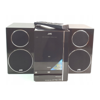
3.1.5 Removing the Headphone board
(See Fig.15)
• Prior to performing the following procedure, remove the rear
cover assembly, the main board and the CD mechanism as-
sembly.
(1) Remove the screw M on the bracket and pull out the head-
phone board.
Fig.15
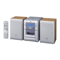
3.1.6 Removing the LCD board
(See Fig.16)
• Prior to performing the following procedure, remove the rear
cover assembly, the main board and the CD mechanism as-
sembly.
(1) Remove the ten screws N and the two screws P on the
Front panel assembly.
Fig.16
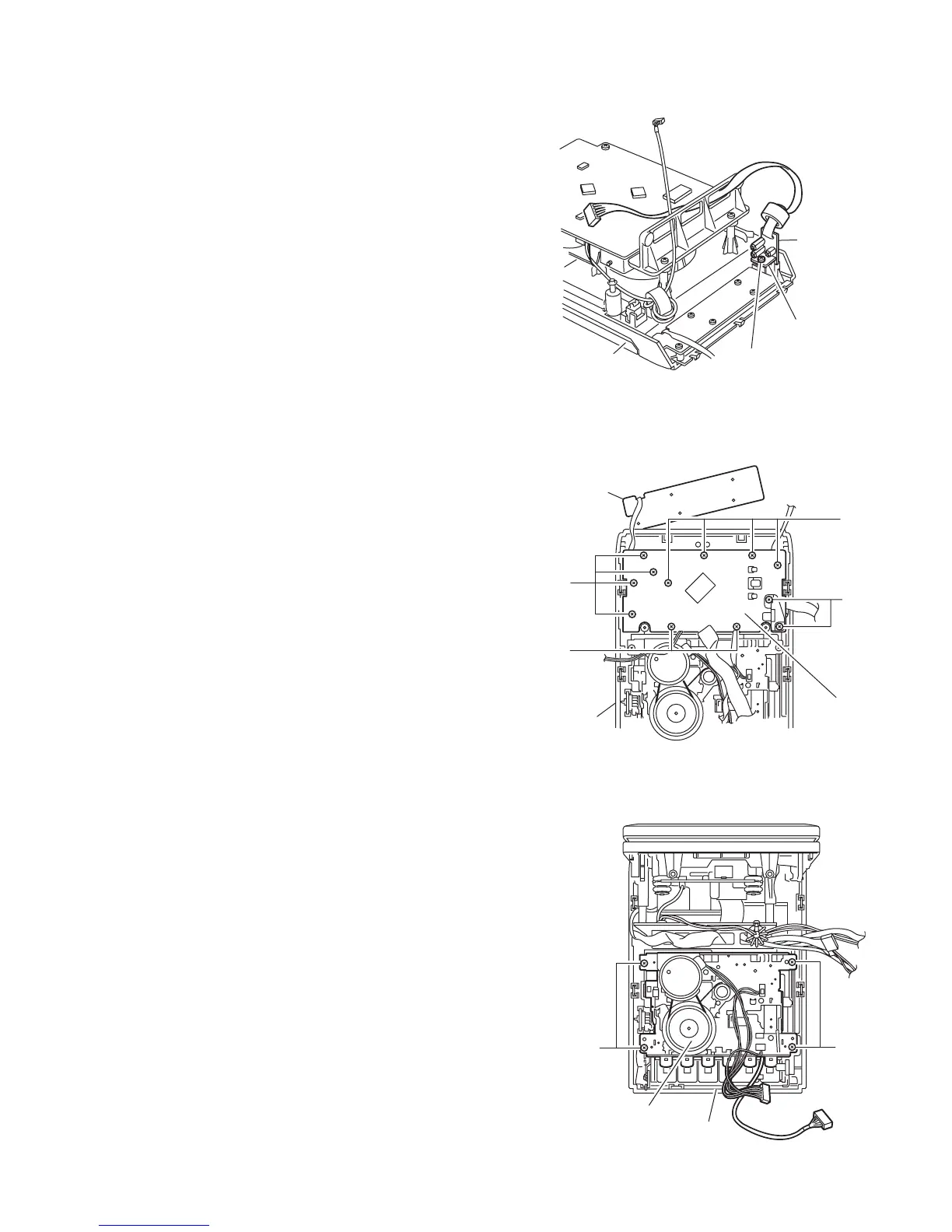
3.1.7 Removing the Cassette mechanism
(See Fig.17)
• Prior to performing the following procedure, remove the rear
cover assembly and the main board.
(1) Remove the four screws Q on the front panel assembly and
press the eject button on the front side to remove the cas-
sette mechanism assembly.
Fig.17
M
Head phones
board
Head phones
bracket
CD mechanism
assembly
Switch board
Front panel
assembly
LCD board
P
N
N
N
QQ
Cassette mechanism
assembly
Front panel
assembly
 Loading...