1-12 (No.MB412)
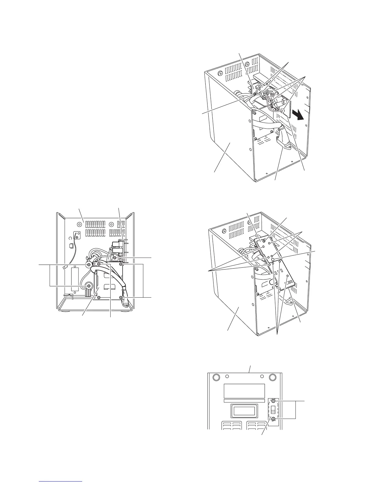
3.1.8 Removing the transformer board
(See Fig.18 to 20)
• Prior to performing the following procedure, remove the rear
cover assembly.
(1) From the rear cover assembly, remove the screw R attach-
ing the transformer board support.
(2) Remove the transformer board from the rear panel assem-
bly in the direction of the arrow.
(3) From the transformer board, remove the screw T attaching
the transformer board support.
(4) Remove the tap attaching the transformer board cover.
(5) Unsolder the eight points on the wire on the transformer as-
sembly.
3.1.9 Removing the transformer
(See Fig. 18,21)
• Prior to performing the following procedure, remove the rear
cover assembly and the transformer board.
(1) From the rear cover assembly, remove the four screws U
attaching the transformer.
(2) Remove the two screws Y setting the power cord.
(3) Remove the two screws A' attaching the voltage selector
on the bottom of the body.
(4) Remove the transformer from the rear panel assembly in
the direction of the arrow.
Fig.18
Fig.19
Fig.20
Fig.21
Transformer
Y
Transformer board
Rear cover assembly
R
U
U
R
Solder point
Solder point
Transformer board
Rear cover assembly
Transformer board support
Voltage selector
Solder point
Solder point
Rear cover assembly
Solder
point
Transformer board cover
Transformer board
Tap
T
A'
Rear cover assembly
Voltage selector
 Loading...