• Tightening torque 0,22…0,25 Nm (2 lb inches)
• Use shielded/drilled cables
• Lay shield on one side of the inverter onto earth
potential
• NPN control is not possible at the A servo !
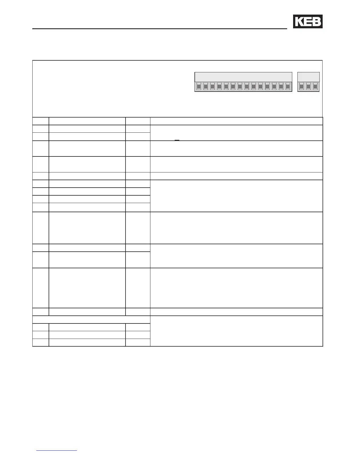
X2A
PIN Function Name Description
1 + Set value input 1 AN1+
Difference voltage
0…±10 V DC ^ 0…±maximum speed, Ri = 55 kΩ
2 - Set value input 1 AN1-
5 Analog output
AN
OUT1
Programmable analog output 0…±10 V DC/ 5 mA.
Function is dened by the machine builder
7 +10V output CRF
Reference voltage output for set value potentiometer
(+10 V DC / max. 4 mA)
8 Analog Mass COM Mass for analog in- and outputs
10 Progr. input 1 I1 The function of the programmable inputs is dened by
the machine builder.
Switching voltage 13…30 V DC ±0 % smoothed
Ri=2,1 kΩ
11 Progr. input 2 I2
12 Progr. input 3 I3
13 Progr. input 4 I4
16
Voltage supply
Driver stage
ST
Supply of the driver stage
This input must be supplied with an external voltage of
20…30
V DC ±0 % / 0,2 A (UBR max. 3,6 Vss). When
switching off this voltage an error reset is executed.
18 Transistor output 1 O1 Programmable digital outputs
Load capacity maximal 50 mA for both outputs.
Function is dened by the machine builder
19 Transistor output 2 O2
21
Voltage supply
Control board
Uin
Supply of the control board
This input must be supplied with an external voltage of
20…30
V DC ±0 % / 0,8 A (UBR max. 3,6 Vss). Through
the separate supply the control can also be operated at
switched off driver/power section.
22 Digital Mass 0V Potential for digital in- / outputs
Relay 1
Programmable relay output (CP.33)
Load capacity max. 30 V DC / 0,01…1 A
Function is dened by the machine builder
24 NO contact RLA
25 NC contact RLB
26 Switching contact RLC
 Loading...


