Installation and Connection
3.5.2 Connection of the control terminal strip
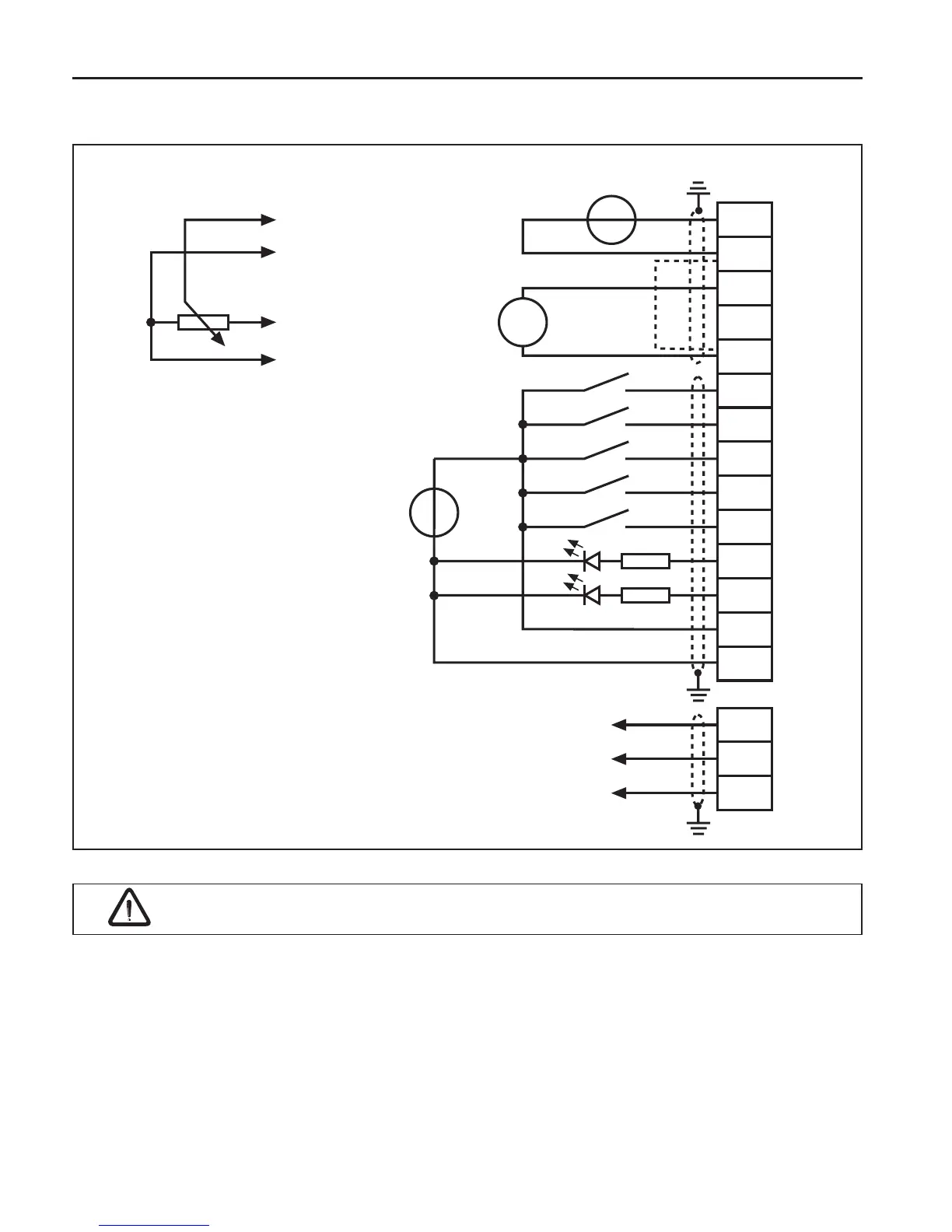
Set value potentiometer
3…10 kΩ
external voltage supply
20…30 V DC ±0 %
1 A
Set value signal
0…±10 V DC
analog output
±10 V DC
max. 5 mA
1)
Connect potential equalizing line only if a potential difference of > 30 V exists between
the controls. The internal resistance is reduced to 30 kΩ.
To avoid interferences a separate shielding must be provided for analog and digital control lines.
Depending on the use of the relay outputs, an extra shielding is to be used, too.
In case of inductive load on the relay outputs a protective wiring must be provided (e.g. free-
wheeling diode) !
The control board must always supply by an external voltage. This keeps the control in
operation even if the power stage is switched off. To prevent undened conditions at external
power supply the basic procedure is to rst switch on the power supply and after that the inverter.
The terminals of the control terminal strip and the transmitter inputs are securely isolated in
accordance with EN 50178.
max. 30 V DC
0.01…1 A
 Loading...


