GB - 14
Technical Data of the 400 V Class
The response threshold of the braking transistsor (Pn.69) for all controls without safe-
ty technology must be adjusted at least to 770 Vdc (see annex D).
2.3.1 DC supply
2.3.2 Calculation of the DC input current
The DC input current of the inverter is basically determined by the used motor. The data can
be taken from the motor name plate.
230V class :
I
DC
=
√3•ratedmotorvoltage•ratedmotorcurrent•Motorcosφ
––––––––––––––––––––––––––––––––––––––––––––––––––––––––––––––––––
DC voltage (310 V)
400V class :
I
DC
=
√3•ratedmotorvoltage•ratedmotorcurrent•Motorcosφ
––––––––––––––––––––––––––––––––––––––––––––––––––––––––––––––––––
DC voltage (540 V)
The DC input peak current is determined by the operating range.
• If you accelerate on the hardware current limit, the short-time current limit of the invert-
er must be used in the formula above (instead of the rated motor current).
• If the motor in normal operation is never stressed with rated torque, it can be calculated
with the real motor current.
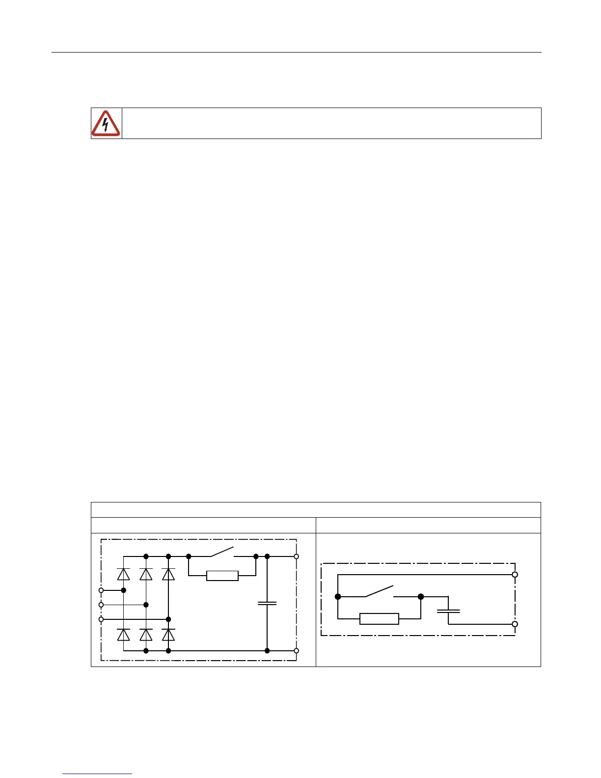
2.3.3 Internal input circuit
The COMBIVERT F5 F6 in U housing corresponds to the inverter type B1. Pay attention to
the inverter type in DC interconnection and in operation at regenerative units.
Inverter type for COMBIVERT F5 F6 in U housing:
Type B1 Type C1

 Loading...


