GB - 26
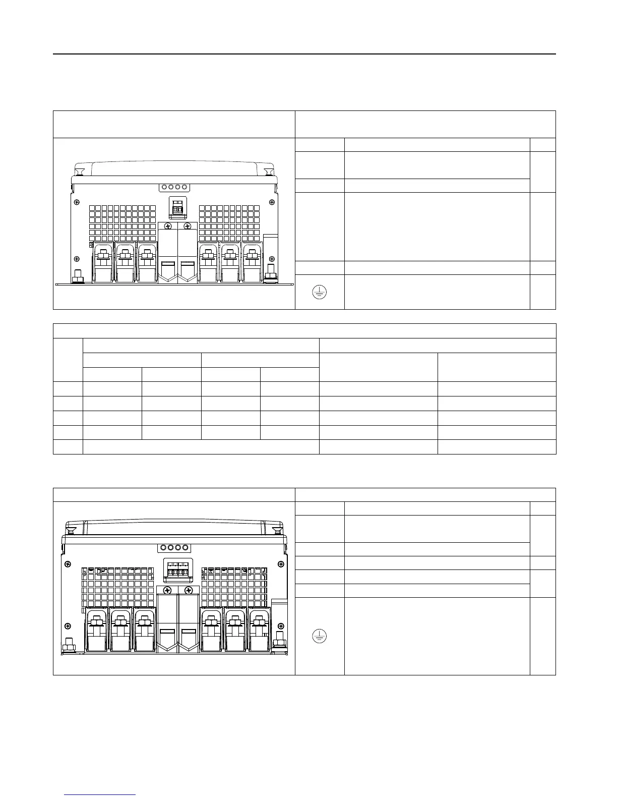
Terminals 400 V Class
Housing size 23…27 DC version without
GTR7
Terminal in accordance with table 2.5
++
+
-
- - U V W
T1
T2
Name Function No.
++, --
DC voltage input
420…746 V DC (400V class)
5
U, V, W Motor connection
+, -
DC link voltage 420…746 V DC
(400V class)
Connection for braking module,
lterorDClinkcoupling
(unsuitable for DC supply)
1
T1, T2 Connection for temperature sensor
3
Connection for shielding / earthing
5
Table 2.5 Permissible cable cross-sections and tightening torques of the terminals
No.
permissiblecross-sectionexiblewithwire-endferrule Maximum tightening torque
mm² AWG/MCM
Nm lb inch
min max min max
1 50 150 1/0 AWG 300 MCM 25…30 270
2 70 240 2/0 AWG 500 MCM 25…30 270
3 0.2 4 24 AWG 10 AWG 0.6 5.3
4 35 95 2 AWG 3/0 AWG 15...20 180
5 10 mm stay bolt for ring thimble 25 220
2.5.2 Terminal strips for 230V units
Unit size 22…24 default with GTR7 Terminal in acc. with table 2.6
L1
L2
L3
PA
PB
U
V W
Name Function No.
L1, L2,
L3
3-phase mains connection
5
U, V, W Motor connection
PA, PB Connection for braking resistor
1
T1, T2 Connection for temperature sensor
3
K1, K2 GTR7 monitoring (optional)
Connection for shielding / earthing
5

 Loading...


