GB - 33
Connection Power Unit
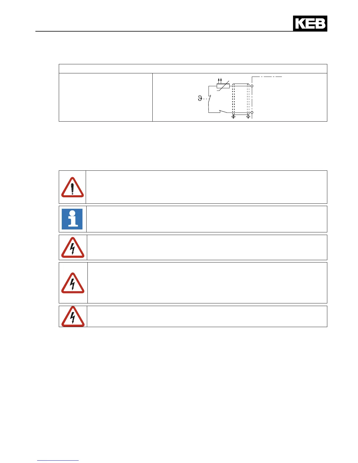
Wiring example in PTC mode
Mixed sensor chain
T1
T2
The function can be switched off with Pn.12 = “7“ (CP.28) if no evaluation of the input is
desired (standard in operating mode GENERAL). Alternatively a bridge can be installed be-
tween T1 and T2.
2.7.5 Connection of a braking resistor
Braking resistors dissipate the produced energy of the motor into heat during gen-
eratoric operation. Thus braking resistors can cause very high surface tempera-
tures. During assembly pay attention to appropriate protection against contact and
re.
The use of a regenerative unit is reasonable for applications which produce a lot
of regenerative energy. Regeneration of excess energy into the mains.
The mains voltage must always be switched o in order to guarantee re protec-
tion in case of a defective braking transistor.
The frequency inverter remains in operation in spite of switched o power sup-
ply in generatoric operation. An error must be released by external wiring which
switches the modulation o in the inverter. This can occur e.g. at terminals T1/T2
or via digital input. The frequency inverter must be programmed accordingly in
each case.
The response threshold of the braking transistsor (Pn.69) for all controls without
safety technology must be adjusted at least to 770 Vdc (see annex D).

 Loading...


