Performance Verification
1-5
1.8.2 AC volts verification
AC voltage accuracy is checked by applying accurate AC
voltages at specific frequencies from an AC calibration
source and then verifying that each Model 2001 AC voltage
reading falls within the specified range. The three ACV ver-
ification procedures that follow include:
• Normal mode
• Low-frequency mode
• Peak ACV
CAUTION
Do not exceed 1100V peak or 2 ×
10
7
V•Hz between INPUT HI and IN-
PUT LO, or instrument damage may oc-
cur.
Table 1-2
Limits for DC volts verification
2001
DCV
range
Applied DC
voltage
Reading limits
(18° to 28°C, 1 year)
200mV
2V
20V
200V
1000V
190.0000mV
1.900000V
19.00000V
190.0000V
1000.000V
189.9918mV to 190.0082mV
1.899949V to 1.900052V
18.99946V to 19.00054V
189.9922V to 190.0078V
999.953V to 1000.047V
Notes:
1. Repeat procedure for negative voltages.
2. Reading limits shown do not include calibrator uncertainty.
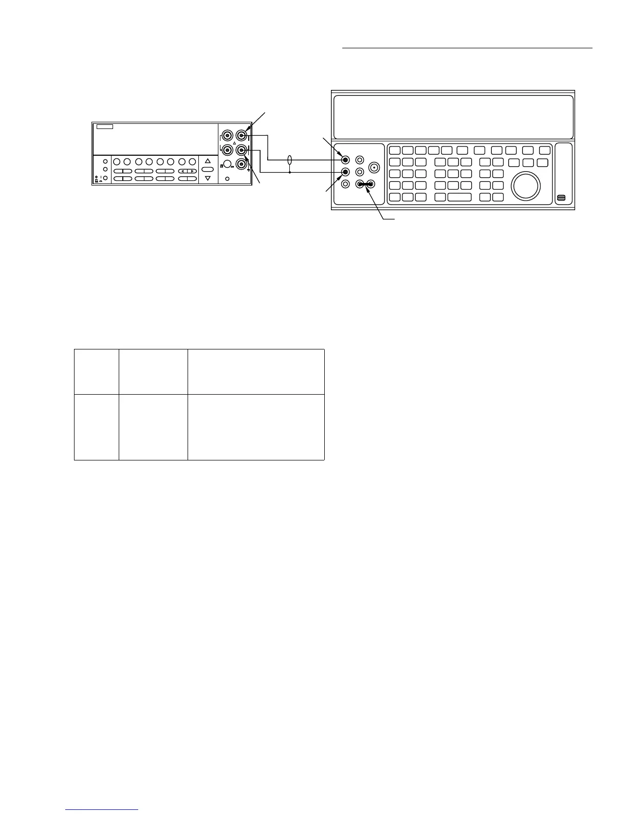
Figure 1-1
Connections for DC volts verification
NEXT
DISPLAY
PREV
POWER
DCV ACV DCI ACI Ω2 Ω4
FREQ TEMP
REL TRIG STORE
RECALL
INFO
LOCAL CHAN SCAN CONFIG MENU EXIT ENTER
RANGE
AUTO
FILTER MATH
RANGE
2001 MULTIMETER
SENSE
Ω 4 WIRE
HI
INPUT
LO
INPUTS
CAL
500V
PEAK
F
R
FRONT/REAR
2A 250V
AMPS
350V
PEAK
1100V
PEAK
+1. 900000 VDC
Input HI
Output HI
Input
LO
Output
LO
Model 2001
5700A Calibrator (Output DC Voltage)
Note: Use shielded, low-thermal cables
when testing 200mV range. Use
internal Guard (EX GRD LED is off).
Ground link installed.
Normal mode
1. Turn on the Model 2001, calibrator, and amplifier, and
allow a one-hour warm-up period before making mea-
surements.
2. Connect the Model 2001 to the calibrator, as shown in
Figure 1-2. Be sure to connect the amplifier HI to Model
2001 INPUT HI, and amplifier LO to Model 2001 IN-
PUT LO as shown. Connect the power amplifier to the
calibrator using the appropriate connector on the rear of
the calibrator.
3. Restore Model 2001 factory default conditions, as ex-
plained in paragraph 1.7.
4. Select the ACV function and the 200mV range on the
Model 2001, and make sure that REL is disabled.
NOTE
Do not use REL to null offsets when per-
forming AC volts tests.
5. Set the calibrator output to 190.000mVAC at a frequen-
cy of 20Hz, and allow the reading to settle.
6. Verify that the Model 2001 reading is within the limits
summarized in Table 1-3.
7. Repeat steps 5 and 6 for 190mVAC at the remaining fre-
quencies listed in Table 1-3 (except 2MHz).Verify that
instrument readings fall within the required limits listed
in the table.
8. Repeat steps 5 through 7 for the 2V, 20V, 200V, and
750VAC ranges, using the input voltages and limits stat-
ed in Table 1-3.
9. Connect the Model 2001 to the wideband calibrator out-
put (Figure 1-3).

 Loading...


