Calibration Programs
B-3
General program instructions
1. With the power off, connect the Model 2001 to the
IEEE-488 interface of the computer. If you are using one
of the programs that controls the Fluke 5700A calibra-
tor, connect the calibrator to the IEEE-488 bus as well.
Be sure to use shielded IEEE-488 cables for bus connec-
tions.
2. Turn on the computer, the Model 2001, and the calibra-
tor. Allow the Model 2001 to warm up for at least one
hour before performing calibration.
3. Make sure the Model 2001 is set for a primary address
of 16. You can check or change the address as follows:
A. Press MENU, select GPIB, then press ENTER.
B. Select MODE, then press ENTER.
C. Select ADDRESSABLE, and press ENTER.
D. If the address is set correctly, press EXIT as neces-
sary to return to normal display.
E. To change the address, use the cursor keys to set the
address to the desired value, then press ENTER.
Press EXIT as necessary to return to normal display.
4. If you are using the Fluke 5700A calibrator over the bus
(Program B-3 through Program B-6), make sure that the
calibrator primary address is at its factory default setting
of 4.
5. Make sure that the computer bus driver software is prop-
erly initialized.
6. Enter the QuickBASIC or Turbo C editor, and type in
the desired program. Check thoroughly for errors, then
save it using a convenient filename.
7. Compile and run the program, and follow the prompts
on the screen to perform calibration.
Unlocking calibration
In order to unlock comprehensive calibration, briefly press in
on the CAL switch with the power turned on. To unlock low-
level calibration, press in and hold the CAL switch while
turning on the power.
Comprehensive calibration
Programs B-1 and B-2 will perform semi-automatic compre-
hensive calibration of the Model 2001 using any suitable cal-
ibrator (see Table B-1 for required calibrator specifications).
Programs B-3 and B-4 will perform comprehensive calibra-
tion almost fully automatically using the Fluke 5700A cali-
brator.
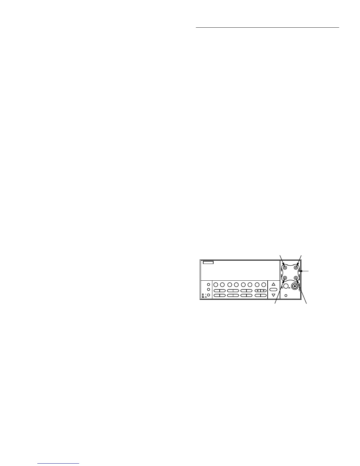
Figure B-1 shows low-thermal short connections, while Fig-
ure B-2 shows calibrator connections.
Low-level calibration
Programs B-5 and B-6 perform low-level calibration using
the Fluke 5700A calibrator. Refer to Figure B-1 and B-3 for
low-thermal short and calibrator voltage connections. Figure
B-4 shows calibrator current connections. Figure B-5 shows
synthesizer connections necessary to supply the 2V AC @
1Hz signal.
NOTE
Low-level calibration is not normally re-
quired in the field unless the Model 2001
has been repaired.
Figure B-1
Low-thermal short connections
NEXT
DISPLAY
PREV
POWER
DCV ACV DCI ACI Ω2 Ω4 FREQ TEMP
REL TRIG STORE RECALL
INFO LOCAL CHAN SCAN CONFIG MENU EXIT ENTER
RANGE
AUTO
FILTER MATH
RANGE
2001 MULTIMETER
SENSE
Ω 4 WIRE
HI
INPUT
LO
INPUTS
CAL
500V
PEAK
F
R
FRONT/REAR
2A 250V
AMPS
350V
PEAK
1100V
PEAK
Model 2001
S+ HI
LOS-
Model 8610
Low-thermal
short

 Loading...


