START/STOP button is an alternate action control that serves
two functions. The two functions are described as follows:
1. When the START/STOP button is pressed the selected pro
.gram mode (step, single or continuous) is initiated.
2. When the START/STOP button is pressed a second time
the START/STOP and the action of the selected program
mode is stopped.
3. The START/STOP LED will be on continuously during the
execution of the single of continuous program mode. In the
step program mode the LED will be on the duration of the
programmed dwell time.
NOTE
When the instrument is in the standby mode
(OPERATE LED is turned off), and either single or
continuous programming mode, the START/
STOP button continues to control the buffer with
no output present on the Model 220. In the step
mode, the START/STOP LED turns on for the
duration of the programmed dwell time.
DATA-The 12 buttons in the Data group allow entry of
numerical data from 0 to 9 including with decimal point and
polarity onto the display,
The TALK, LISTEN and REMOTE LED’s identify the pre-
sent status of the IEEE-488 bus. For more information con-
cerning the Model 220 and the IEEE-488 bus refer to the
Model 220/230 Programming Manual.
2.3.3 Rear Panel Description
OUTPUT connector is Teflon@ insulated female triax con-
nector.
GUARD terminal provides a low impedance voltage source
which is equal to the output compliance voltage. The max-
imum load oapcitence for the guard output is O.OlhF. The max-
imum load current which includes guard and output is not to
exceed 106mA. The accuracy of the guard output is f 1mV
excluding output lead IR voltage drops.
NOTE
The guard voltage will not equal the output
voltage when the instrument is at the programm-
ed V-limit overcompliance level.
DIGITAL l/O port consists of four input end four output lines
as well as IEEE-488 common and +5VDC. The outputs will
drive one TTL load. The instrument can be programmed to
generate an SRQ upon any change in the 4 bit input data.*
EXTERNAL TRIGGER INPUT initiates the selected program
mode in the same manner as the START/STOP button upon
receiving a TTL level negative transition with a minimum pulse
width of lO@ec.
EXTERNAL TRIGGER OUTPUT provides a negative TTL
level pulse of greater than lO@ec at the completion of the pro-
grammed dwell time.
The line power fuse is rated as shown in Tables 52 and 53.
The line plug mates with a 3-wire line cord which provides UL
approved connections to line power.
*For more information concerning the IEEE488 connector,
digital I/D port and primary address switches refer to the
Model 220/230 Programming Manual.
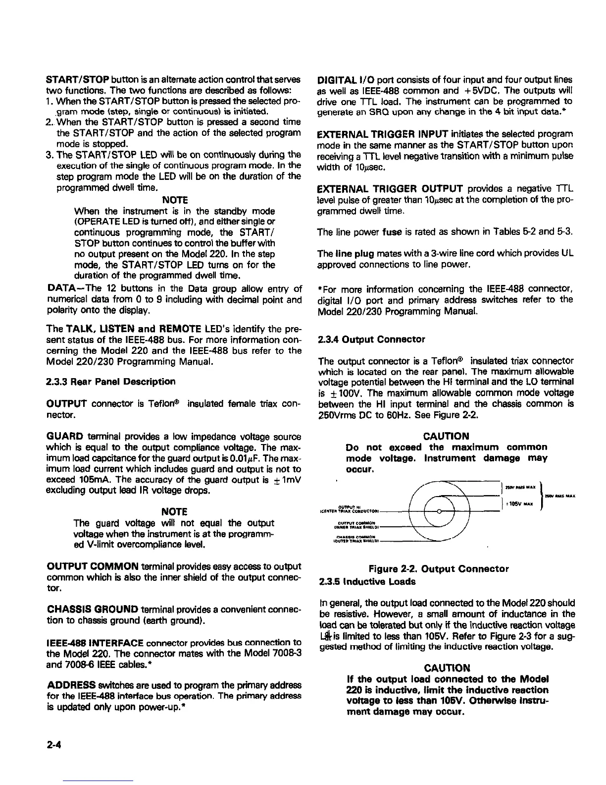
2.3.4 Output Connector
The output connector is a Teflon@ insulated triax connector
which is located on the rear panel. The maximum allowable
voltage potential between the HI terminal and the LO terminal
is f 1OOV. The maximum allowable common mode voltage
between the HI input terminal and the chassis common is
25OVrms DC to 60Hz. See Figure 2-2.
CAUTION
Do not exceed the maximum common
mode voltage. Instrument damage may
occur.
OUTPUT COMMON terminal provides easy access to output
common which is also the inner shield of the output connec-
Figure 2-2. Output Connector
tor.
23.5 Inductive Loads
mvenient connec-
In general, the output load connected to the Model 220 should
be resistive. However, a small amount of inductance in the
load can be tolerated but only if the inductive reaction voltage
IEEE-W INTERFACE connector provides bus connection to
L&is limited to less than 105V. Refer to Figure 2-3 for a sug-
the Model 220. The connector mates with the Model 70083
gested method of limiting the inductive reaction voltage.
and 70066 IEEE cables.*
AYY~CJJ swrcnes are use0 10 program me r ADDRESS switches are used to program the primary address
for the IEEE-488 interface bus operation. The c for the IEEE-488 interface bus operation. The primary address
is “dated only ,._^_ - -...__ .._ *
is updated only upon power-up.*
If the output load connected to the Model
220 is inductive, limit the inductive reaction
voltage to lass than 106V. Otherwise instru-
ment damage may occur.
2-4

 Loading...


