b. Unplug the ribbon cable (J/P10031 from the analog
board.
c. Remove the bonom shield of the analog board by
removing the two phillips head screws that secure the
shield to the board.
NOTE
Do not remove the input cable.
6. Place the analog board along the side of the Model 220.
7. Remove the mother board from the case.
a. Remove the four plastic standoffs.
b. Remove the two phillips head screws that secure the
mother board to the case. They are located at the rear
of the mother board one by the fan and the other is by
the line voltage selector switch S102.
c. Remove the two phillips head screws that secure the
case to the rear panel.
d. Unplug the display ribbon cable fJ/PlOOZ) from the
mother board.
e. Grasp the mother board and the rear panel
simultaneously. Lift the mother board and rear panel
up and toward the rear of the instrument. Then lift the
mother board and rear panel out of the case.
8. Remove the display board.
a. Remove the two phillips head screws that secure the
display board to the front panel.
b. Remove the front panel bunons.
c. Lift the display board out of the case.
9. For reassembly, perform steps 1-8 in reverse order.
NOTE
When installing connectors J/P1004, J/P1003
and J/P1002 be sure to align pin one of the
connector to pin one of the cable.
5.6 FAN FILTER MAINTENANCE
The internal temperature generated by the Model 220
necessitates the forced air cooling provided by the fan. The
fan has an sir filter which keeps the Model 220 relatively free
of dust and dirt. Dust and dirt collect on the filter and im-
pede the air flow through the instrument. Lack of air flow
will cause overheating. Therefore, the filter must be kept
clean in order for the Model 220 to achieve optimum perfor-
mance. To clean the filter:
1. Remove the filter from the fan.
2. Use compressed air to remove the dust and dirt from the
filter. If the filter is excessively dirty wash it in mild soap
and water and dry it with compressed air.
3. Reinstall the filter.
5.7 SPECIAL HANDLING OF STATIC SENSITIVE
DEVICES
MOS devices are designed to function at high impedance
levels. Normal static charge can destroy these devices.
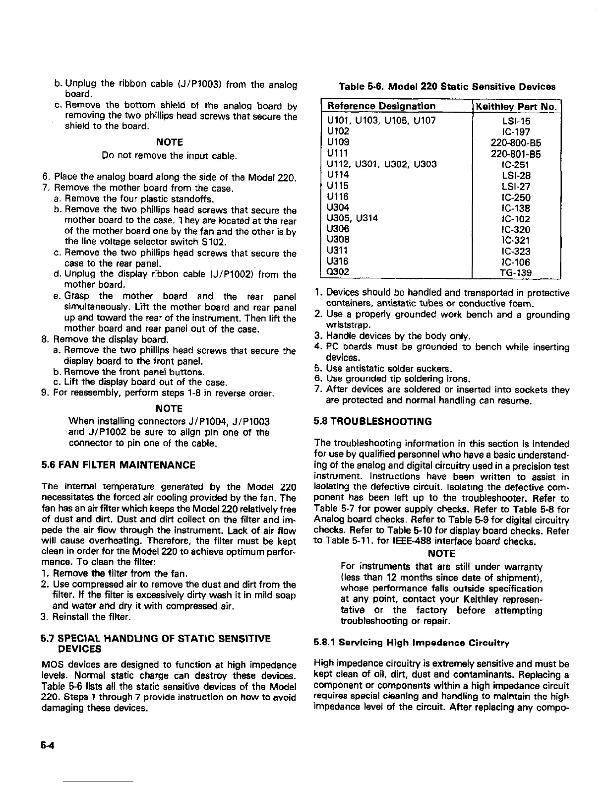
Table 5-6 lists all the static sensitive devices of the Model
220. Steps 1 through 7 provide instruction on how to avoid
damaging these devices.
5-4
Table 5-6. Model 220 Static Sensitive Devices
Reference Designation
UlOl, u103. u105, u107
u102
u109
Ulll
U112, U301, U302, U303
u114
u115
U116
u304
u305, u314
U306
U308
u311
U316
MO2
Leithley Part No.
LSI-15
IC-197
220-800-85
220-801-85
IC-251
LSI-28
LSI-27
IC-250
IC-138
IC-102
IC-320
IC-321
IC-323
IC-106
TG-139
1. Devices should be handled and transported in protective
containers, antistatic tubes or conductive foam.
2. Use a properly grounded work bench and a grounding
wriststrap.
3. Handle devices by the body only.
4. PC boards must be grounded to bench while inserting
devices.
5. Use antistatic solder suckers.
6. Use grounded tip soldering irons.
7. After devices are soldered or inserted into sockets they
are protected and normal handling can resume.
5.8 TROUBLESHOOTING
The troubleshooting information in this section is intended
for use by qualified personnel who have a basic understand-
ing of the analog and digital circuitry used in a precision test
instrument. Instructions have been written to assist in
isolating the defective circuit. Isolating the defective com-
ponent has been left up to the troubleshooter. Refer to
Table 5-7 for power supply checks. Refer to Table 5-8 for
Analog board checks. Refer to Table 59 for digital circuitv
checks. Refer to Table 5-10 for display board checks. Refer
to Table 5-11. for IEEE-488 interface board checks.
NOTE
For instruments that are still under warranty
(less than 12 months since date of shipment),
whose performance falls outside specification
at any point, contact your Keithley represen-
tative or the factory before attempting
troubleshooting or repair.
5.8.1 Servicing High Impedance Circuitry
High impedance circuitry is extremely sensitive and must be
kept clean of oil, dirt, dust and contaminants. Replacing a
component or components within a high impedance circuit
requires special cleaning and handling to maintain the high
impedance level of the circuit. After replacing any compo-

 Loading...


