5.2.5 Calibration Adjustments
Use the following procedure end make the adjustments in-
dicated to calibrate the Model 220. To locate adjunment
points, remove the top cover and refer to the analog board
shield.
WARNING
To prevent a shock hazard, turn the instru-
ment off, remove the line cord and all test
leads from the instrument before remov-
ing the top cover.
1. Remove the top cover (see paragraph 5.5, step II. Werm-
up with top cover in place. Minimize the time the cover is
removed.
2. Short the output of the Model 220 (HI to LO). Monitor
the guard output with the Model 192 (Item A Table 5-l)
on the .2VOC range. Program the Model 220 for an out-
put of + .OOOO-3 amps and a compliance of IOV. Locate
and adjust R343 for a reading on the Model 192 of
.oooooo f 20/&v.
3. Remove the short from the output and connect the
Model 220 and Model 192 as shown in Figure 5-1. Pro-
gram the Model 220 output +.OOOO-3 amps. Monitor
the Model 220 output on the Model 192. Invert the
Modal 220 output (press + and ENTER on the Model
220) and note the change in current. Calculate the
average reading when the output is changed from
positive to negative and adjust R304 for the calculated
value. Then adjust R392 for a reading of less than
5. Remove the current measurement test configuration and
monitor the Model 220 output with the Model 192 on the
200VDC range. Program the Model 220 to + 19,OOOE-6
amps and a compliance of 1OOV. Adjust R319 for a
reading of 100.000 f 0.2V.
6. This completes the calibration of the Model 220. To
verify correct calibration refer to Section 3.
r--------i
I -
I
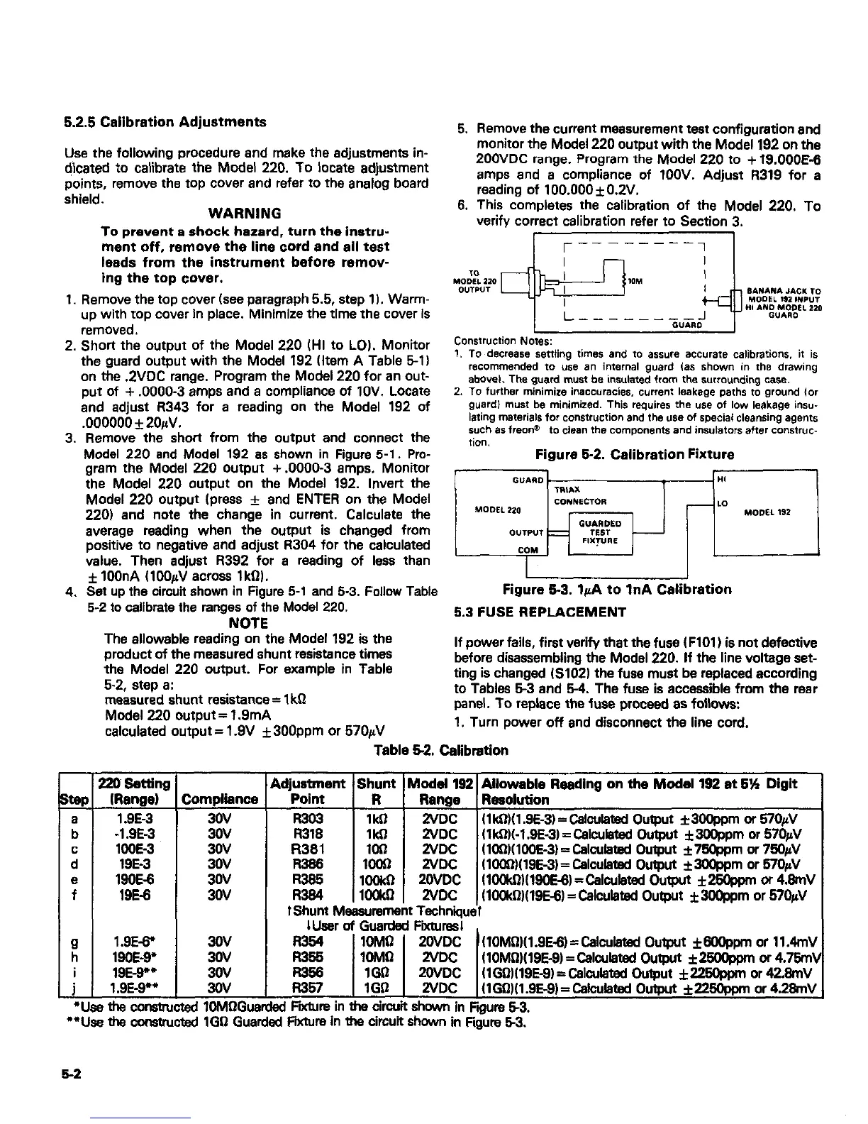
Construction Noms:
1. TO decrease settling times and 10 assure accurafe calibmtions. it is
recommended to “se an internal guard Ias show” in d,e drawing
abovel. The guard must be insulated from the wrraunding case.
2. To futihe, minimize inaccumcies, current leakage paths to ground IO,
guardl must be minimized. This requires the use of low leakage insu-
lath9 materials for construction and the use of special cleansing agents
such as freona to clean the components and insulators after consl,uc-
lion.
Figure 52. Calibration Fixture
f IOOnA ClOO$J across 1kG).
I
I
4. Set up the circuit shown in Figure 5-1 and 5-3. Follow Table
Figure 53. IpA to InA Calibration
5-2 to calibrate the ranges of the Model 220.
5.3 FUSE REPLACEMENT
NOTE
The allowable reading on the Model 192 is the
product of the measured shunt resistance times
If power fails, first verify that the fuse ( FlOl ) is not defective
the Model 220 output. For example in Table
before disassembling the Modal 220. If the line voltage set-
5-2, step a:
ting is changed IS1021 the fuse must be replaced according
measured shunt resistance = IkQ
to Tables 6-3 and 6-4. The fuse is accessible from the rear
Model 220 output = 1.9mA
panel. To replace the fuse proceed as follows:
calculated output = 1.9V f 300ppm or 570~1V
1. Turn power off and disconnect the line cord.
-
E?!
E
:
e
f
Lf
0
L
l 1
-1
6-2
-I-
120 Eettlng
IRange)
1 .SE-3
-1.8E-3
looE-3
19E-3
WOE-6
19E-8
1.9E-6’
WOE-9’
19~9””
1 .SE-p*
(
:ompliince
3OV
3ov
3ov
3ov
3ov
L
3OV
30V
::
3OV
I ms cansbucted 1OMGGua
I ths constucted 1GG Gual
Table 5-2. Calibration
idjustment 1 Shunt 1 Model 192 1 Allowable
Reading on
the Model 192 at 6% Digit
Point 1
R 1 Range lResdutfon
R303 1 1kG 1
2VDC 1 (lkG)(l .SE-3) = Calculated Output i3Ogpprn or 57OuV
I.7318 1kS-I 2VDC (lkWl.SE-3) = Calculated Ou+ut **pm or 57&/
R38l
I?386 i%I
2VDC 1lOG~WWE-3l= Calculatsd Output *76@pm or 76OpV
2VDC WlOG1~18&3~= Calculated Output *3O@pm or 670#
R386
1OW-l
20VDC KUNdIWOEB)=Calurlatad Output &2Wppm or 4.8mV
R384 lOWI
2VDC
11OWGWE-6~ = Calculated Output f3Wppm or 67OfiV
IShunt Measurement Technique1
I User of Guarded Fochrasl
kzi
10MG
20VDC (lOMG)(l.8E-6)=Calculatsd Output H9Oppm or 11.4mV
1OMi-l 2VDC fl0MG)(18E-8j=Calculatad Output *woqYnn or 4.76m\
zig
1GG 20VDC (lGlW19E-9) = Calculatad Output f226@pm or 42.8mV
IGO 2VDC
~lG~)l1.8E-9)=Calcuiatad Output f225@pm or 4.28mV
xi F&m in tha circuit shown in Faum 6-3.
d Fnbre in ths circuit shown in Figure 53.

 Loading...


