2
Matrix Switching Basics
2-1
2.1 Introduction
This section covers the basics for matrix switching and
is arranged as follows:
2.2 Basic matrix conÞguration:
Covers the basic 4
×
10 matrix conÞguration. The signiÞcance of the
backplane jumpers is also covered here.
2.3 Typical matrix switching schemes:
Explains
some of the basic ways a matrix can be used to
source or measure. Covers single-ended switch-
ing, differential (ßoating) switching, and sensing.
2.4 Matrix expansion:
Discusses the various matrix
conÞgurations that are possible by using multi-
ple cards.
2.2 Basic matrix configuration (4
×
10)
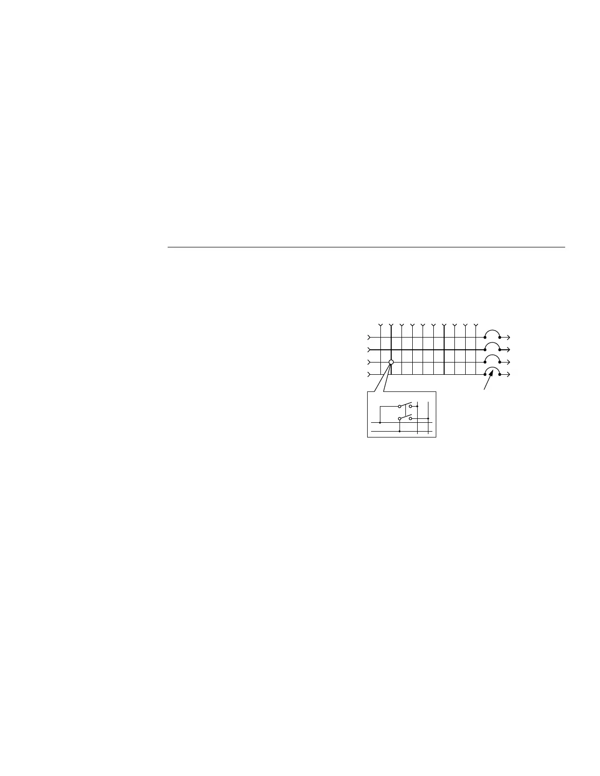
A simpliÞed schematic of the Model 7012 matrix card
is shown in Figure 2-1. The card is conÞgured as a 4
×
10 matrix. Each of the 40 crosspoints is made up of a
two-pole switch. By closing the appropriate crosspoint
switch, any matrix row can be connected to any col-
umn in the matrix.
Backplane jumpers
Notice in Figure 2-1 there are four pairs of backplane
jumpers located on the relay card. With the jumpers in-
stalled, the matrix card is connected to the analog back-
plane of the Model 7001 allowing matrix expansion
with a second 7001 card installed in the mainframe.
With the jumpers removed (cut), the matrix card is iso-
lated from another card installed in the mainframe.
Figure 2-1
Model 7012 simplified schematic
110
1
2
3
4
Rows
23456789
Column
To 7001
Analog
Backplane
HI
LO
Crosspoint (1 of 40)
Backplane
Jumpers
(4 pairs)
Artisan Scientific - Quality Instrumentation ... Guaranteed | (888) 88-SOURCE | www.artisan-scientific.com
 Loading...


