Service Information
5-6
7. Install the Model 7012 in the Model 7001 slot 1 and
turn the Model 7001 on.
8. Allow the Models 7012, 7001, and 182 to warm up
for two hours.
9. Select the 3mV range on the Model 182.
10. Press REL READING on the Model 182 to null out
internal offsets. Leave REL READING enabled for
the entire procedure.
11. Turn the Model 7001 off. Remove the Model 7012
front slot 1. Cut the short from HI to LO on the
rows.
12. Install the Model 7012 in the Model 7001 slot 1 and
turn power on.
13. Wait 15 minutes.
14. Program the Model 7001 to close Channel 1!1!1.
15. After settling, verify that the reading on the Model
182 is <500mV (7012-S). This measurement repre-
sents the contact potential of the pathway.
16. From the Model 7001, open Channel 1!1!1.
17. Repeat steps 14 through 16 for all 40 crosspoints.
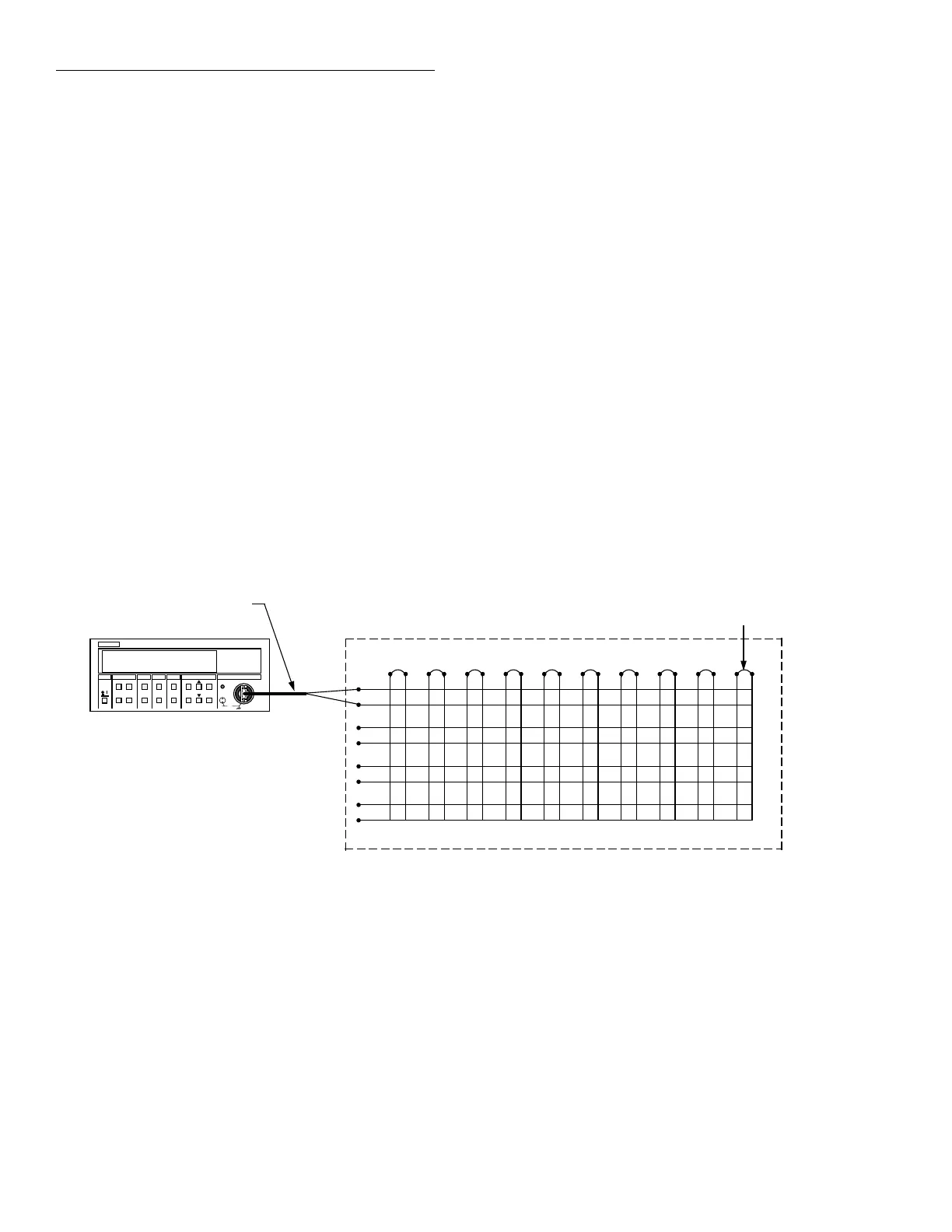
Figure 5-4
Contact potential testing
1
2
3
4
1 3456789102
Model 7012
HI
LO
Note : Setup shown is configured
to test Row 1 crosspoints
for contact potential.
Model 1484
Low Thermal Cable
(Unterminated)
Low Thermal short-
clean high purity
copper (1 of 10)
Rows
Columns
HL HL HL HL HL HL HL HL HL HL
H
L
H
L
H
L
H
L
KEITHLEY
182 SENSITIVE DIGITAL VOLTMETER
TRG
SRQ
REM
TALK
LSTN
Model 182
5.3.6 Contact potential tests
These tests check the EMF generated by each relay con-
tact pair (H and L) for each pathway. The tests simply
consist of using a sensitive digital voltmeter (Model
182) to measure the contact potential.
Perform the following procedure to check contact po-
tential of each path:
1. Turn the Model 7001 off if it is on.
2. Place a short between HI to LO on each input col-
umn 1-10.
3. Connect all row HI together on the common bus.
4. Connect all row LO together on the common bus.
5. Place a short between HI to LO on the rows.
6. Connect the Model 182 input leads to HI and LO of
the rows.
Artisan Scientific - Quality Instrumentation ... Guaranteed | (888) 88-SOURCE | www.artisan-scientific.com
 Loading...


