2400-902-01 (G - Feb 2006)
Model 2400 Service Manual 4-6
Troubleshooting
Power supply
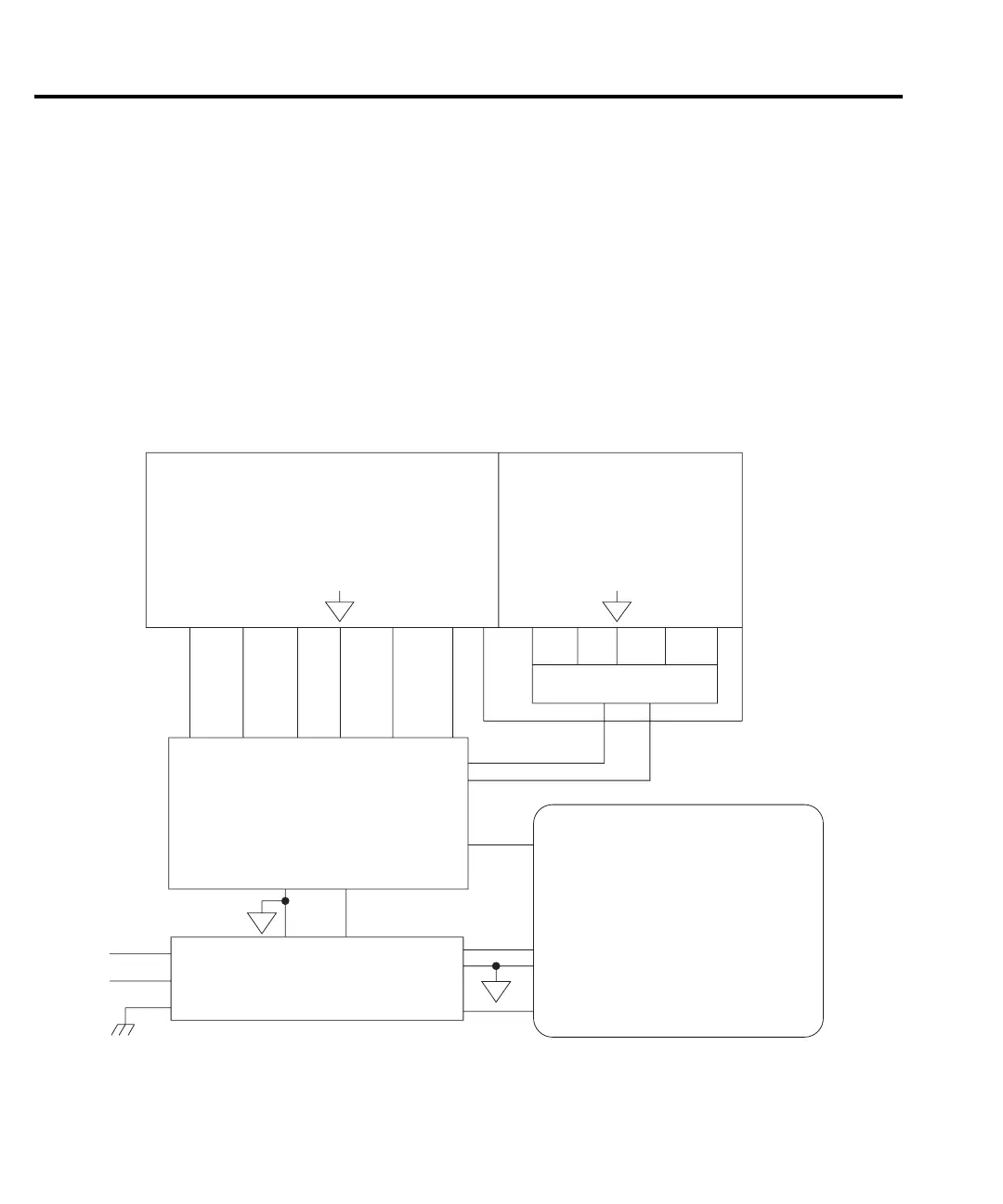
Figure 4-2 shows a block diagram of the Model 2400 power delivery system.
The offline flyback switching power supply provides all power for the instrument while provid-
ing universal inputs for the 110/120V line. The digital board runs directly from the switcher,
including the +12VD supply. (See Digital circuitry.)
A constant-frequency switching supply runs off the +12VD supplies and generates all the float-
ing supply voltages for the analog board: +5VF, ±15VF, and ±30VF. An AC output (low volt-
age) supplies the analog board with the power it uses to derive the output stage supply voltages,
±36VO and ±220VO.
Analog Board
Output Stage
Constant Frequency
Low Noise Floating
Switching Supply
+12Vd
Line
Neutral
Switching Power
Supply
+12Vd
+5Vd
D
D
High Voltage/
Power
Digital Circuits
AC1
AC2
O
F
+30V
F
-30V
F
+15V
F
-15V
F
-220 +220+36 +36+5V
F
gure
4-
Power supply block diagram

 Loading...