EasyManua.ls Logo

Keithley 2400 Service Manual

Keithley 2400
137 pages
To Next Page IconTo Next Page
To Previous Page IconTo Previous Page
Page #19 background image
2400-902-01 (G - Feb 2006)
1-7 Model 2400 Series User’s Manual
Performance Verification
The “real” compliance condition can occur when the compliance setting is less than the highest
possible reading of the measurement range. When in compliance, the source output clamps at
the displayed compliance value. For example, if the compliance voltage is set to 1V and the
measurement range is 2V, the output voltage will clamp (limit) at 1V.
“Range” compliance can occur when the compliance setting is higher than the possible reading
of the selected measurement range. When in compliance, the source output clamps at the
maximum measurement range reading (not the compliance value). For example, if the
compliance voltage is set to 1V and the measurement range is 200mV, the output voltage will
clamp (limit) at 210mV.
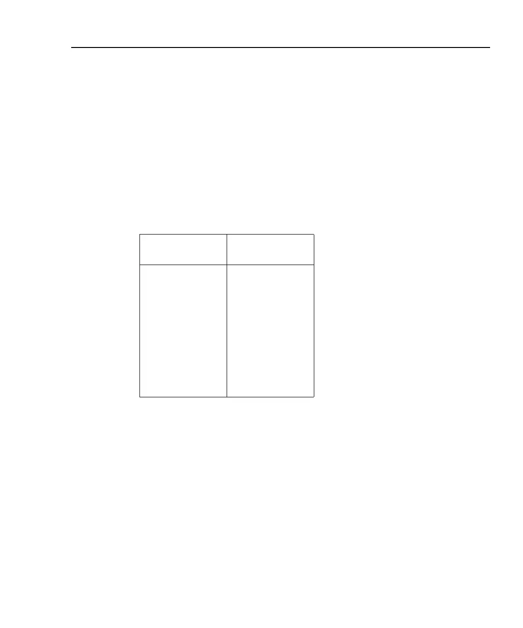
Maximum compliance values
The maximum compliance values for the measurement ranges are summarized as follows:
Measurement
range
Maximum
compliance value
200mV
2V
20V
200V
1µA
10µA
100µA
1mA
10mA
100mA
1A
210mV
2.1V
21V
210V
1.05µA
10.5µA
105µA
1.05mA
10.5mA
105mA
1.05A
When the SourceMeter goes into compliance, the “Cmpl” label or the units label (i.e., “mA”)
for the compliance display will flash.
Determining compliance limit
The relationships to determine which compliance is in effect are summarized as follows. They
assume the measurement function is the same as the compliance function.
Compliance Setting < Measurement Range = Real Compliance
Measurement Range < Compliance Setting = Range Compliance
You can determine the compliance that is in effect by comparing the displayed compliance
setting to the present measurement range. If the compliance setting is lower than the maximum
possible reading on the present measurement range, the compliance setting is the compliance
limit. If the compliance setting is higher than the measurement range, the maximum reading on
that measurement range is the compliance limit.

Table of Contents

Questions and Answers:

Keithley 2400 Specifications

General IconGeneral
Model2400
CategorySourceMeter
Voltage Source Range±200 V
Power Output20 W
Voltage Measurement Resolution100 nV
Current Measurement Resolution10 pA
Resolution5.5 digits
InterfacesGPIB, RS-232
Current Source Range±1A
Current Measurement Range±1A
Resistance Measurement Range2 Ω to 200 MΩ
DisplayVacuum Fluorescent Display

Summary

Warranty

Manual Print History

Safety Precautions

Performance Verification

Introduction

Explains the purpose and conditions for verifying performance.

Recommended test equipment

Lists required verification equipment with specifications.

Performing the verification test procedures

Details the steps for executing verification tests.

Test summary

Lists the types of accuracy tests performed.

Calibration

Introduction

Explains calibration procedures and requirements.

Calibration considerations

Provides important notes for performing calibration.

Unlocking calibration

Details how to unlock the calibration function.

Changing the password

Explains how to change the calibration password.

Viewing calibration dates and calibration count

Explains how to view calibration history.

Calibration errors

Discusses potential calibration errors and messages.

Front panel calibration

Details the procedure for front panel calibration.

Step 2. Voltage calibration

Provides detailed steps for voltage calibration.

Step 3. Current calibration

Provides detailed steps for current calibration.

Routine Maintenance

Line fuse replacement

Provides instructions for replacing the line fuse.

Troubleshooting

Front panel tests

Explains tests for keys and display functionality.

KEYS test

Tests the functionality of each front panel key.

DISPLAY PATTERNS test

Verifies the vacuum fluorescent display functionality.

Analog circuits

Describes the analog circuitry block diagram.

Battery replacement

Provides instructions for replacing the internal battery.

Disassembly

Handling and cleaning

Provides precautions for handling and cleaning.

Static sensitive devices

Explains handling of static-sensitive devices.

Case cover removal

Provides steps to remove the instrument's case cover.

Analog board removal

Provides steps to remove the analog board.

Removing power components

Details procedures for removing power supply and module.

Replaceable Parts

Parts lists

Refers to tables for electrical parts and mechanical assemblies.

Ordering information

Details information needed for ordering parts.

Specifications

2400, 2400-LV and 2400-C SourceMeter® Specifications

Core technical specifications for the instrument.

SOURCE SPECIFICATIONS

Details specifications for source functions.

MEASURE SPECIFICATIONS

Details specifications for measure functions.

SYSTEM SPEEDS

Details instrument speed performance.

Accuracy calculations

Measure accuracy

Explains how to calculate measurement accuracy.

Source accuracy

Explains how to calculate source accuracy.

Command Reference

Command summary

Summarizes Model 2400 calibration commands.

Miscellaneous commands

Describes commands for saving, locking, and programming dates.

Detecting calibration errors

Explains how to detect calibration errors.

Detecting calibration step completion

Methods to detect calibration step completion.

Calibration Programs

Computer hardware requirements

Lists required computer hardware for programs.

Software requirements

Lists required computer software for programs.

General program instructions

Provides general instructions for running programs.

Program C-1. Model 2400 calibration program

Provides a BASIC program for calibration.

Related product manuals