4-8 Troubleshooting Model 2500 Service Manual
Power supply
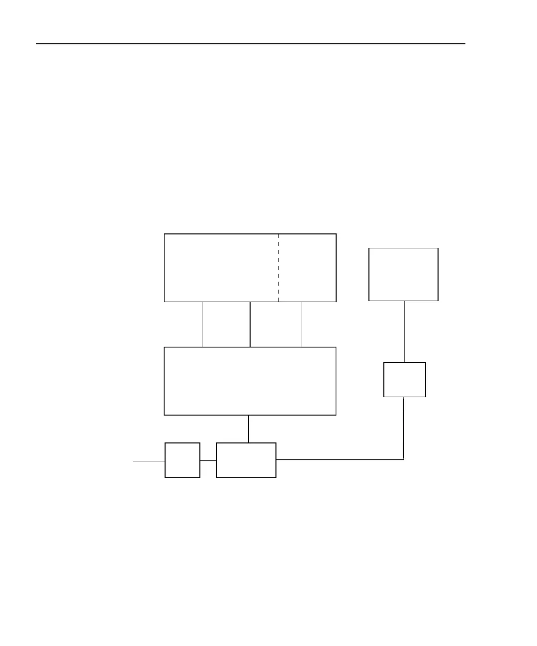
Figure 4-3 shows a block diagram of the Model 2500 power supply system.
NOTE There are two identical power supply systems in the Model 2500, one for each
channel. Only one power supply is shown in Figure 4-3.
Regulated circuits include ±5V and ±15V to power the analog circuits, and a separate
+5VD supply to power digital circuits. Unregulated ±110V supplies power to the bias
source output stages.
Figure 4-3
Power supply block diagram
Channel 1 or 2
Analog Circuits
±5V
+5VD
Line In
Line
Filter
Digital
Circuits
Digital
Supply
Power
Transformer
100/120/220/
240V AC
Channel 1 or 2
Analog Supplies
±15V
±110V
Voltage
Source
Output
Stage
Note: One channel shown

 Loading...


