8: Grading and binning resistors DMM6500 6½ Digit Multimeter
8-4 DMM6500-900-01Rev. A / April 2018
Trigger model template: grade and binning test
The trigger model template contains the settings for the number of components, digital I/O, and limits.
The command parameters for the template are described in the following command and table.
SCPI command usage:
:TRIGger:LOAD "GradeBinning", <components>, <startInLine>, <startDelay>,
<endDelay>, <limit1High>, <limit1Low>, <limit1Pattern>, <allPattern>,
<limit2High>, <limit2Low>, <limit2Pattern>, <limit3High>, <limit3Low>,
<limit3Pattern>, <limit4High>, <limit4Low>, <limit4Pattern>, "<bufferName>"
TSP command usage:
trigger.model.load("GradeBinning", components, startInLine, startDelay, endDelay,
limit1High, limit1Low, limit1Pattern, allPattern, limit2High, limit2Low,
limit2Pattern, limit3High, limit3Low, limit3Pattern, limit4High, limit4Low,
limit4Pattern, bufferName)
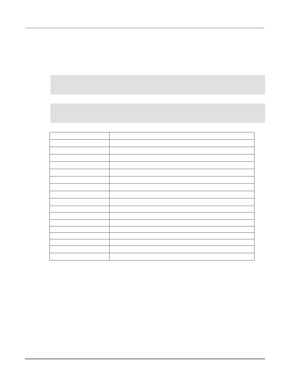
Parameter list
Digital I/O line 5
100 ms
R = 100 Ω, P = 20%, 100+20% = 120 Ω
R = 100 Ω, P = 20%, 100-20% = 80 Ω
Bin 1 Fail Pattern 15: drive all digital I/O lines high (1111)
All Pass Pattern 4: drive line 3 high (0100)
R = 100 Ω, P =10%, 100+10% = 110 Ω
R = 100 Ω, P =10%, 100-10% = 90 Ω
Bin 2 Fail Pattern 1: drive line 1 high (0001)
R = 100 Ω, P =5%, 100+5% = 105 Ω
R = 100 Ω, P =5%, 100-5% = 95 Ω
Bin 3 Fail Pattern 2: drive line 2 high (0010)
R = 100 Ω, P =1%, 100+1% = 101 Ω
R = 100 Ω, P =1%, 100-1% = 99 Ω
Bin 4 Fail Pattern 3: drive line 1 and 2 high (0011)
The reading buffer is set to

 Loading...