EasyManua.ls Logo

Kenwood TK-7360 User Manual

Kenwood TK-7360
24 pages
To Next Page IconTo Next Page
To Previous Page IconTo Previous Page
Page #2 background imageLoading...
Page #2 background image
Terminal Descriptions
ACC (D-SUB 15 Pin Connector)
No. Name I/O Description 6SHFLÀFDWLRQ
1 SB O DC Power Output 13.6 V ±15%
2 IGN I Igintion Signal Input
Power On: Over 8 V
Power Off: Under 6 V
3 PA O Loudspeaker Output ї
4 DO O Audio Output 500 mV
p-p
5 DI I Audio Input Nї
6 FNC1 I/O Programmable High Impedance
7 FNC2 I/O Programmable High Impedance
8 FNC3 I/O Programmable High Impedance
9 FNC4 I/O Programmable High Impedance
10 FNC5 I/O Programmable High Impedance
11 FNC6 I/O Programmable High Impedance
12 5C O DC Power Output 5 V, Max 100 mA
13 HR1 O Horn Alert Signal Output Max 3 A
14 HR2 O Horn Alert Signal Output Max 3 A
15 GND Ground Ground
6SHDNHU-DFNPP3KRQH-DFN:ї
No. Name I/O Description 6SHFLÀFDWLRQ
1 SPO O External Speaker Output ї
3 GND Ground Ground
DC Input Connector
No. Name I/O Description 6SHFLÀFDWLRQ
Red B I DC Power Input 13.6 V ±15%
Black GND I Ground Ground
Microphone Jack
No. Name I/O Description 6SHFLÀFDWLRQ
1 MBL O Backlight of Microphone
2 SB O DC Power Output 13.6 V ±15%
3 GND Ground Ground
4 PTT I/O PTT/ PC Serial Data from Radio High Impedance
5 ME Mic Ground Ground
6 MIC I Mic Signal Input ї
7 HOOK I Hook/ PC Serial Data to Radio High Impedance
8 DM I/O Mic Data Detection High Impedance
Antenna Terminal
їLPSHGDQFH

Other manuals for Kenwood TK-7360

Question and Answer IconNeed help?

Do you have a question about the Kenwood TK-7360 and is the answer not in the manual?

Kenwood TK-7360 Specifications

General IconGeneral
BrandKenwood
ModelTK-7360
CategoryTransceiver
LanguageEnglish

Summary

Terminal Descriptions

User Notices and Safety

Safety Precautions

Highlights hazards common to transceiver operation, including RF exposure.

Precautions

Fire and Injury Prevention

Advises on preventing fire, personal injury, and equipment damage during use.

Electrical System Compatibility

Warns about operating in 12V negative ground systems and using correct power cables.

Getting Started

Preparation and Warnings

Covers vehicle preparation and warnings related to RF energy and installation.

Power Cable Connection

Details the steps for connecting the DC power cable to the vehicle battery.

Installing the Transceiver

Mounting Bracket Installation

Instructions for marking, drilling, and attaching the mounting bracket.

Cable and Antenna Connections

Steps for connecting the antenna and power cable to the transceiver.

Getting Acquainted

Front Panel Overview

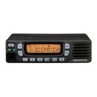
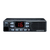
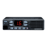
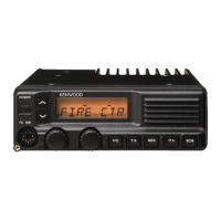
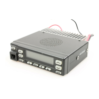
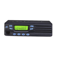
Identifies and describes the front panel controls and indicators of the transceiver.

Programmable Functions

Function List

Lists the functions that can be programmed to the transceiver keys.

Switching Power On/Off

Instructions for switching the transceiver power on and off.

Basic Operations

Transceiver Password Management

Details how to enter, set, and confirm a transceiver password.

Selecting Zones and Channels

Describes methods for selecting zones, channels, and group IDs.

Transmitting and Receiving

Guides on initiating calls, transmitting, and receiving using the microphone.

Telephone and Scan Operations

Making Telephone Calls

Steps for initiating and conducting telephone calls via the transceiver.

Scan Management and DTMF Calls

Signaling and Stun Functions

FleetSync and Selcall Operations

Advanced Operations

Emergency Call Procedures

How to initiate emergency calls and the transceiver's response.

Advanced Transceiver Features

Signal Adjustment and Alerts

VGS-1 Voice Guide & Storage Unit

VGS-1 Voice Guide Features

Mandatory Safety Instructions

RF Exposure Compliance

Instructions for complying with FCC RF exposure limits and safe antenna mounting.

Antenna Installation Guidelines

Requirements for antenna mounting and substitution to ensure safety.

Related product manuals