23
TK-890/
(
B
)
/H
(
B
)
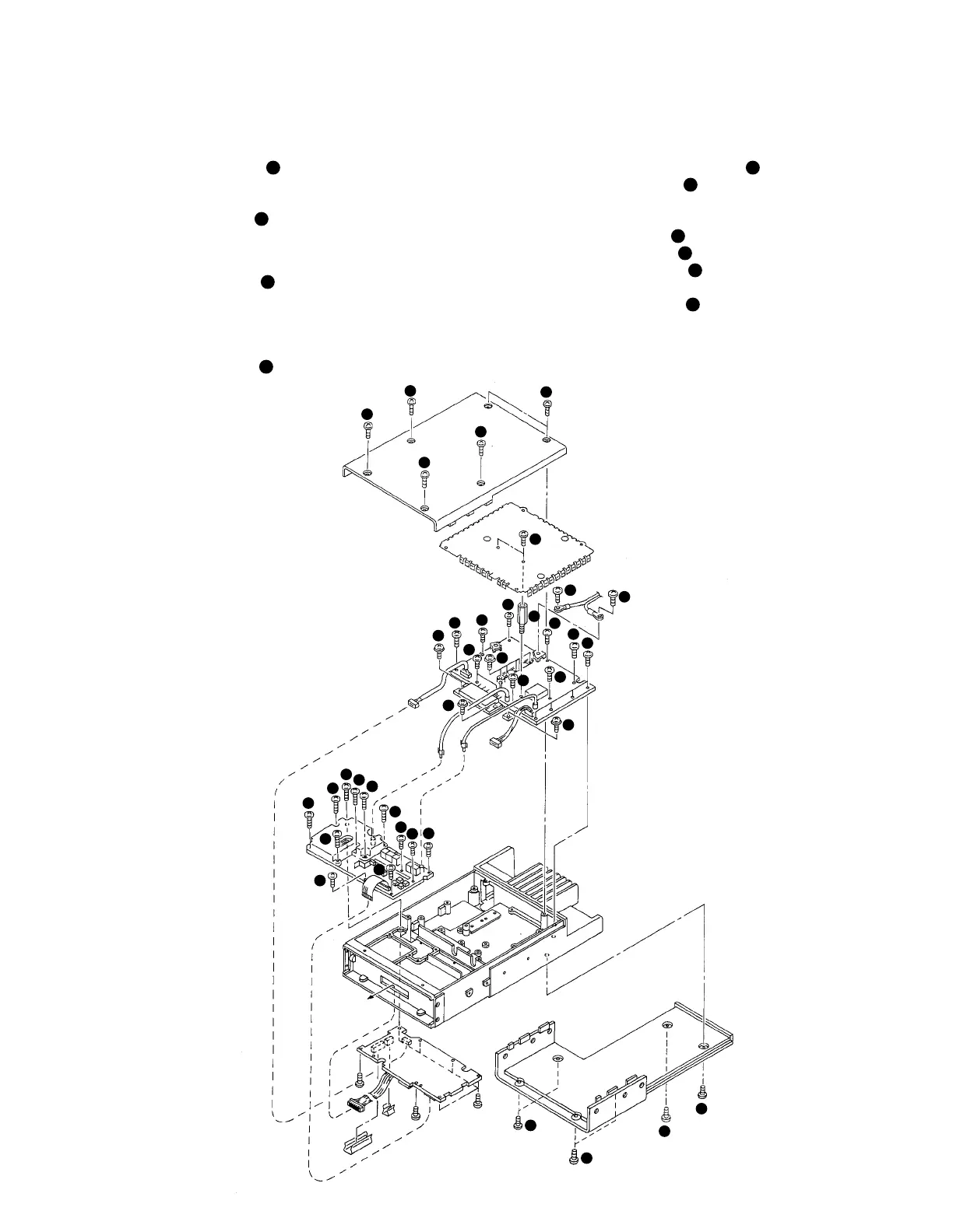
DISASSEMBLY FOR REPAIR (TK-890H(B))
1. Removing the Case and Shield Cover
1. Remove the 12 screws (
1
), and remove the upper and
lower halves of the case. (Remove the 6 screws holding
the upper half and the 6 screws holding the lower half.)
2. Remove the 2 screws (
2
), and remove the shield cover.
2. Removing the TX-RX Unit (X57-562 A/3)
1. Remove the 7 screws (
3
), and remove the PLL shield
case.
2. Remove the connector (CN201) and coaxial plugs
(CN104, CN203) from the final unit, and remove the flat
cable (CN202) upwards from the control unit (CN502).
3. Remove the 5 screws (
4
).
3. Removing the Final Unit (X45-357)
1. Remove the 2 hexagonal bosses (
5
).
2. Remove the 3 screws (
6
) holding the power module
and transistor to the frame.
3. Desolder the power module.
4. Remove the 1 screw (
7
) holding TH1.
5. Remove the 4 screws (
7
) holding the final transistor.
6. Remove the 2 screws (
8
) holding the lead terminal
from DC connector (4P) on the rear.
7. Remove the 13 screws (
9
) holding the PC board.
8. Desolder W3 on the antenna connector.
1
1
1
1
1
2
8
8
9
9
9
9
9
9
9
9
9
6
3
3
3
3
3
3
3
4
4
4
4
4
1
1
1
1
6
6
7
5
CN203
Control
unit
TX-RX
unit
Final
unit
CN104
CN201
 Loading...