24
TK-890/
(
B
)
/H
(
B
)
DISASSEMBLY FOR REPAIR
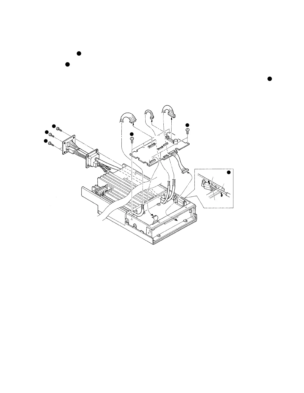
4. Removing the Control Unit (X57-562 B/3)
1. Remove the 8 screws (
1
).
2. With a screwdriver, remove the 2 leaf springs holding the
ICs to the frame (
2
).
3. Remove the flat cable (CN502).
4. Remove the 2 connectors CN501 and CN506.
5. Remove the connector (CN505) from D-sub connector
(25P) on the rear.
1
3
3
3
1
2
Leaf spring
Screw-
driver
IC
CN502
CN501
CN506
CN505
5. Removing the Accessory Connector on
the Rear
1. Confirm that the screw holding +DC cable (red) and the
screw holding –DC cable (black) of the final unit are re-
moved, and that CN506 of the control unit (X57-562 B/3)
is disconnected. Remove the 4 screws on the rear (
3
).
2. Pull out the connector. (Take the connector terminals out
through the opening in the frame.)
 Loading...