TS-480HX/480SAT
5
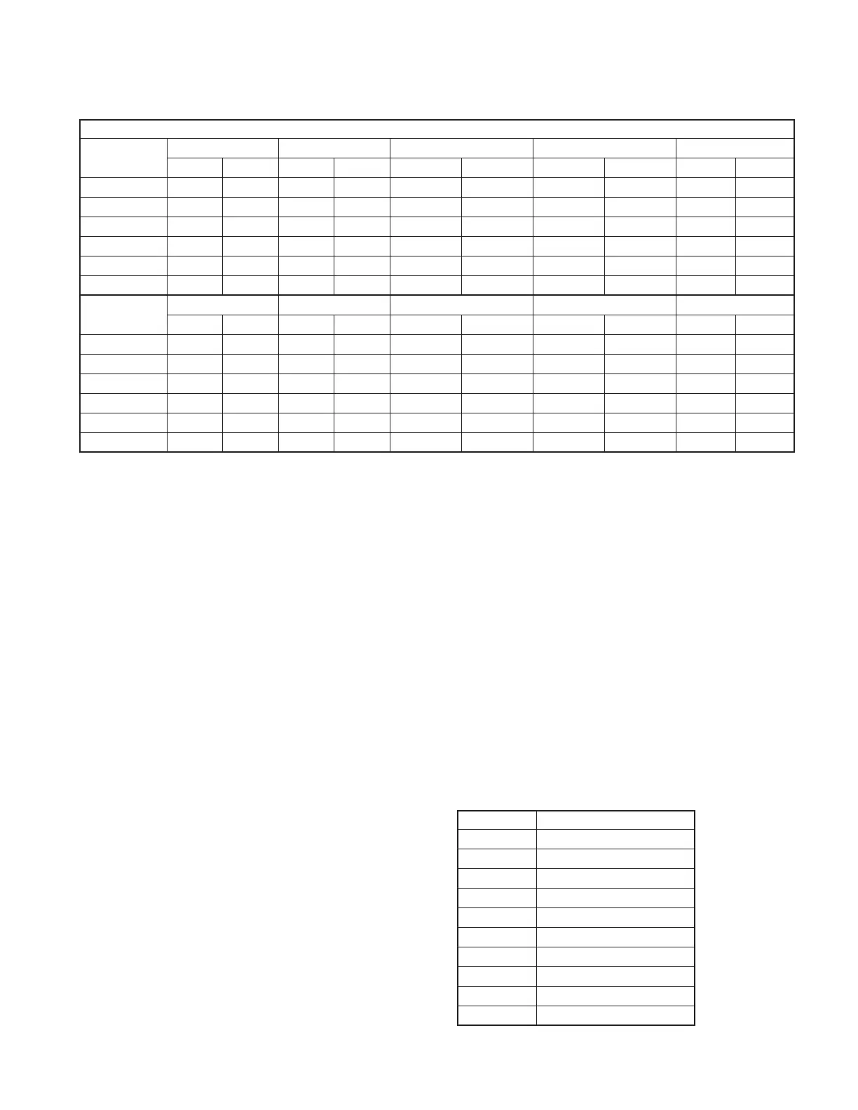
DDS AD9835BRU (IC2)
CAR USB LSB CW CW-R CWN
RX TX RX TX RX TX RX TX RX TX
Filter offset 1 +1.5k +1.5k -1.5k -1.5k
+(1.5k-PITCH) +(1.5k-PITCH) -(1.5k-PITCH) -(1.5k-PITCH)
00
Filter offset 2 +0.71k +0.71k -0.71k -0.71k - - - - - -
CW piitch - - - - +(PIITCH) - -(PIITCH) - +(PIITCH) -
FSK tone - - - - - - - - - -
IF Shift +(IF S) - -(IF S) - +(IF S) - -(IF S) - +(IF S) -
CAR correction
+(CAR H) +(CAR H) -(CAR L) -(CAR L) +(CAR H) +(CAR H) -(CAR L) -(CAR L) - -
CAR CWN-R FSK FSK-R AM FM
RX TX RX TX RX TX RX TX RX TX
Filter offset 1 0 0 -(SHIFT/2) -(SHIFT/2) -(SHIFT/2) -(SHIFT/2) Stop 0 -455k 0
Filter offset 2 - - - - - - - - - -
CW pitch -(PIITCH) - - - - - - - - -
FSK tone - - -(MARK) -(MARK)
+(MARK+SHIFT)
-(MARK) - - - -
IF Shift -(IF S) - -(IF S) - +(IF S) - - - - -
CAR correction
---- - - - - - -
Filter offset 2 : DATA filter ON, The amount of IF shift when selecting Center “2210Hz”
(∆ RIT) : RIT frequency variable amount (-9.99~+9.99kHz)
(∆ XIT) : XIT frequency variable amount (-9.99~+9.99kHz)
(PITCH) : CW pitch frequency (400~1000Hz, Initial value 800Hz)
(SHIFT) : FSK shift width frequency (170Hz, 200Hz, 425Hz, 850Hz, Initial value:170Hz)
(MARK) : FSK mark frequency (H TONE : 2125Hz, L TONE : 1275Hz, Initial value : 2125Hz)
Table 2 CAR frequency shift data
Receiver Circuit
FM mode operates in a triple conversion: the first IF
(73.095MHz), the second IF (10.695MHz), and the third IF
(455kHz). All modes other than FM mode operate in a double
conversion: the first IF (73.095MHz), and the second IF
(10.695MHz).
■ From antenna to a preamplifier (Q153, 154)
There are two antenna terminals: ANT 1 and ANT 2. With
these antenna terminals, it is possible to select the terminal
to be used and store the selection for each band. A pigtail
wire is used in this transceiver to maintain the freedom of the
antenna wire when it is mounted in a car.
The receive signal sent from the antenna terminal enters
the ANT section (X45-366 C/3 : 200W transceiver, X45-365 C/
3 : 100W transceiver) of the final unit. The signal passes
through a surge trap, the antenna changeover relay, the an-
tenna tuner changeover relay (only 100W transceiver), the
transmission/reception changeover relay, and an image filter,
and is then sent from CN503 to CN2 of the RF unit (X44-327)
though a co-axial cable.
The signal input into the RF unit passes through the at-
tenuator circuit, the image filter, the surge absorption limiter,
and then enters the RF BPF. Although the default of the at-
tenuator is 12dB, it can change to approximately 20dB by re-
moving the CN4 jumper.
The RF BPF divides in the range as shown in table 3. The
transmit signal also passes through the RF BPF when trans-
mitting.
The preamplifier (Q153, 154) receives the signal passed
through the RF BPF. This transceiver obtains necessary gain
and frequency characteristic by applying NFB (Negative
Feedback) to the source earthed circuit having two parallel-
connected MOS FETs. Although the preamplifier was con-
ventionally switched by switching between low-band and
high-band, this transceiver can obtain necessary characteris-
tics for each band by switching the NFB amount of the
source at Q155.
You can turn the preamplifier ON/OFF by pressing the
[ATT/PRE] key.
Band Filter range
BC 30kHz~1.705MHz
1.8MHz 1.705~2.5MHz
3.5MHz 2.5~4.1MHz
7MHz 4.1~7.5MHz
10MHz 7.5~10.5MHz
14MHz 10.5~14.5MHz
21MHz 14.5~21.5MHz
28MHz 21.5~30MHz
30~49MHz, 54~60MHz
50MHz 49~54MHz
Table 3 RF BPF
CIRCUIT DESCRIPTION
 Loading...