TS-480HX/480SAT
58
Updating the Firmware
■ System requirements
• PC (Windows 95/ 98/ 98SE/ Me/ NT 4.0/ 2000/ XP)
• RS-232C straight cable
• Update software ”TS480UPDATE_S.EXE”
■ Note
1. Execute the full reset to ensure consistency with the
backup data after updating the Firmware.
2. When you do not want to remove data such as memory
channel data, save the data using the ARCP-480 before
updating the Firmware and write the data after updating
the Firmware.
■ Operating procedure
1. Disconnect the power cable from the transceiver.
2. Remove the upper case of the transceiver.
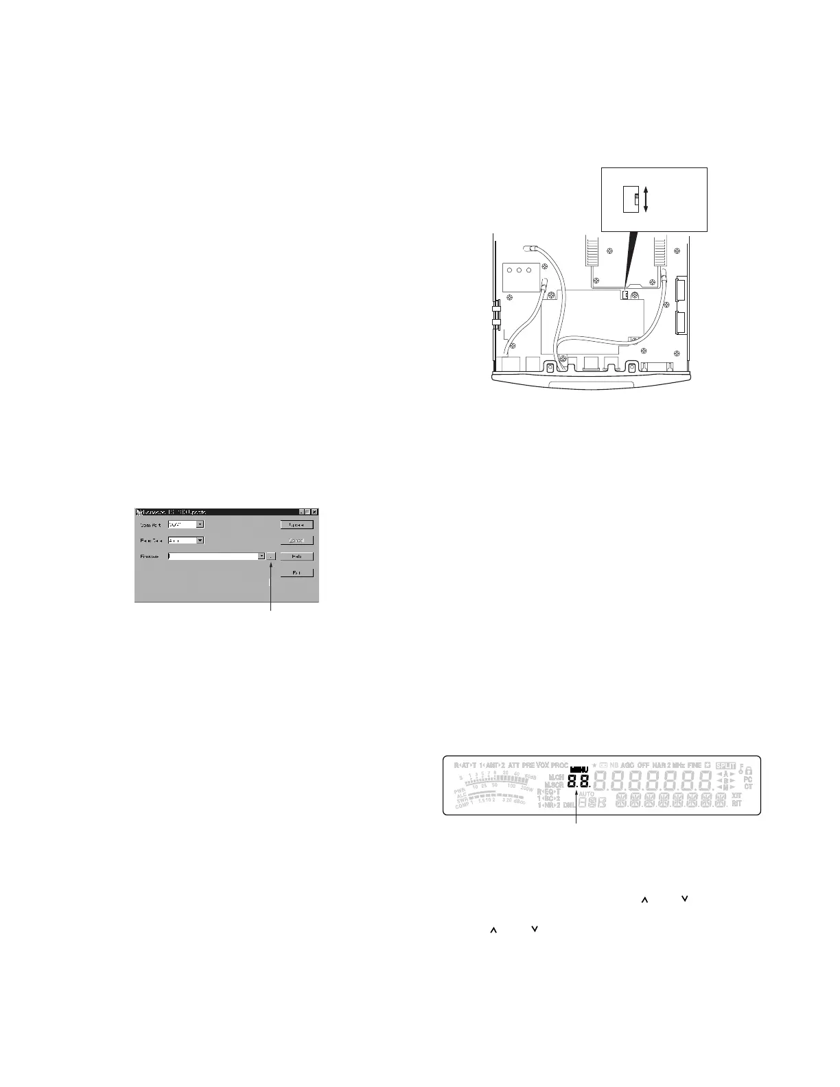
3. Set the slide switch (S201) of the TX-RX unit (X57-663 A/2)
to ON (move the switch toward the front ).
4. Connect the RS-232C terminal of the PC and the trans-
ceiver’s COM terminal via a RS-232C straight cable.
5. Connect the power cable with the transceiver.
Run the ”TS480UPDATE_S.EXE”. The following display
appears.
“File reference” button
7. Change the “COM Port” setting if necessary.
8. Change the “Baud Rate” setting if necessary. (Normally,
select “Auto”, but change it to a slower baud rate if com-
munication errors frequently occur.)
9. Click the “File reference” button and select the firmware
to be written (.bin file).
10. Click the [Update] button to start writing. (When an error
occurs during updating, disconnect and connect the
power cable to reset the MCU. Then, click the [Update]
button again.)
11. Disconnect the RS-232C straight cable and the power
cable from the transceiver after completing writing.
12. Set the slide switch (S201) of the TX-RX unit (X57-663 A/
2) to OFF (move the switch toward the rear ).
13. Replace the upper case, which was removed in step.2,
onto the transceiver.
14. Reconnect the power cable, which was disconnected in
step.11, to the transceiver.
15. Perform the full reset. (Turn the transceiver ON while
pressing the [A=B] key, then press the [A=B] key again
when the reset confirmation message appears.)
16. Turn the transceiver OFF.
17. Check the checksum. (Turn the transceiver ON while
pressing the [MIC] key and [NR] key, to enter checksum
confirmation mode. The checksum of the updated firm-
S201
OFF (Normal)
ON (Update)
ware appears on the 7 segment display while the [M-
CHKSUM] appears on the 13 segment display.)
18. Turn the transceiver OFF.
Adjustment Mode
■ Outline
1. You can adjust the transceiver in service adjustment
mode (adjustment using the panel keys) or with manual
adjustment (turning a coil and a trimmer, etc).The service
adjustment mode (hereinafter referred to as “adjustment
mode”) has 79 items (Menu No. 00 to 78) and all adjust-
ment data is stored in the EEPROM (X57-663 A/2 : IC202).
2. Enter adjustment mode and change each setting data.
3. New data will be written the EEPROM by performing
Menu No. 76 writing.
■ Operation procedures in adjustment mode
1. How to start the adjustment mode
• Insert the adjustment jig (W05-0611-00) into the DATA
connector located on the front panel of the transceiver.
• Turn the transceiver ON while pressing the [MIC] key and
[NR] key, to enter adjustment mode and the Menu No.
appears on the Memory Channel No. display.
Remove the adjustment jig from the transceiver when the
Menu No. appears.
Menu No.
2. Select adjustment mode Menu No.
Turn the [MULTI] knob to change the Menu No.
3. Change adjustment mode setting data
Setting data can be changed with [
] or [ ] key.
4. Write adjustment mode data
Press [ ] or [ ] key on the main unit or [UP] or [DWN]
key on the microphone on Menu No. 76.
5. Cancel adjustment mode
Press the [MTR] key to return to the normal VFO mode.
Note: When the power is turned OFF in the middle in the
adjustment mode, it is canceled.
ADJUSTMENT
 Loading...