TP-6195 1/0434 Section 6 Installation
Use a 12-volt battery with a minimum rating of 675 cold
cranking amps at 0 _F. The generator set uses a
negative ground with a 12-volt engine electrical system.
See Figure 6-15 for battery connections. Make sure
that the battery is correctly connected and the terminals
are tight.
Note: The generator set will not start and circuit board
damage may occur if the battery is connected in
reverse.
Figure 6-16 shows the location of the engine starting
battery. Standard battery cables provide easy
connection to the battery. Use the following procedure
to install and connect the battery.
Battery Installation Procedure
1. Ensure that the starting battery is fully charged
before placing the battery in service.
2. Clean the battery posts and/or adapters if
necessary.
3. Install the battery post adapters, if needed.
4. Place the battery in the housing.
5. Verify that the controller master s witch is in the OFF
position.
EZ-273000-J
1
2
1. To positive (+) terminal on starter solenoid.
2. To ground (--) terminal on or near starter motor.
Figure 6-15 12-Volt Engine Electrical System Single
Starter Motor Typical Battery Connection
6. Connect the positive (+) lead to the engine starting
battery.
7. Connect the negative (--) lead to the engine starting
battery.
Refer to Section 3.8 for battery maintenance
instructions.
6.9.5 Battery Charger
The generator set requires an external battery charger
to keep the starting battery fully charged. A 6-amp
battery charger is factory-installed in the battery
compartment. The battery charger’s DC leads are
factory-connected.
Plug the battery charger’s power cord into a 120 VAC
outlet on the load side of the system. Refer to Section
2.5 for battery charger operation information.
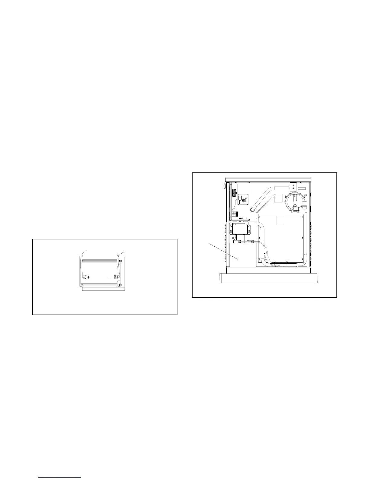
1
GM29253
1. Engine starting battery location
Figure 6-16 Battery Location, Air Intake End

 Loading...


