TP-6195 1/04 35Section 6 Installation
6.10 Accessories
Have accessories installed by an authorized
distributor/dealer or a licensed electrician. Follow the
installation instructions provided with each kit. Use
separate conduit for AC and DC leads to reduce the
possibility of electrical interference. Verify that the leads
and conduit do not interfere with the operation of the
generator set or obstruct the service areas. Verify that
the electrical installation complies with the National
Electrical Code (NEC) and all applicable local and state
codes. See Section 5, Wiring Diagrams, for more
information regarding generator set electrical
connections.
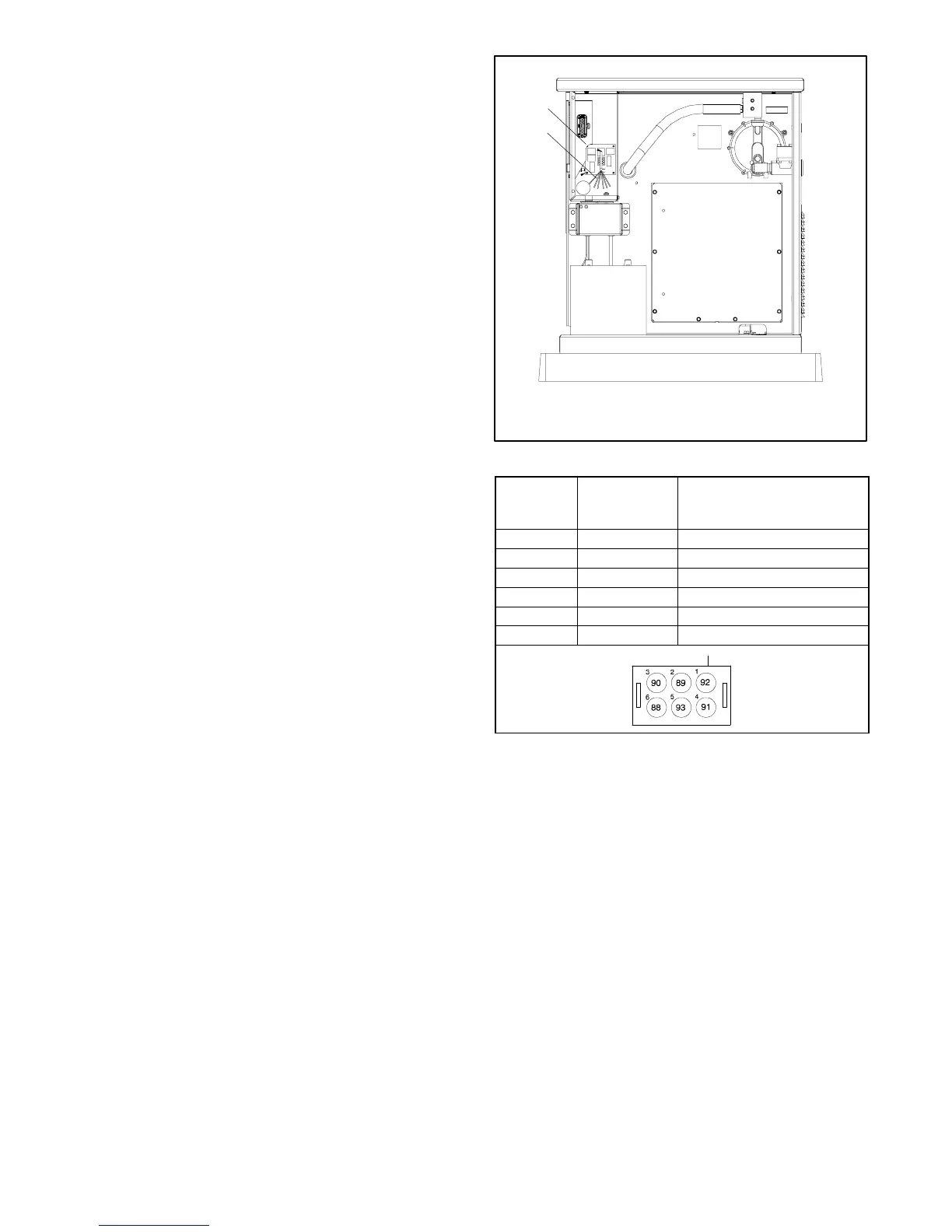
6.10.1 Common Fault and Run Relay
Board
The optional relay board provides two additional relays
to control customer-provided equipment:
D Common fault relay
D Auxiliary run relay
The optional relay board replaces the standard relay
board. The relay board location is shown in Figure 6-17.
Connect customer equipment to the relay board
harness. Figure 6-18 lists the customer connections.
The common fault relay is energized on a fault. The
auxiliary run relay is energized when the generator set is
running. Connect to each relay’s normally open or
normally closed contacts depending on the application.
1
GM30414
1. Relay board
2. Relay board harness
2
Figure 6-17 Common Fault and Run Relay Board
Harness
Lead
Number
Connector
Pin Number
Connection
88 6 Common fault normally open
89 2 Common fault common
90 3 Common fault normally closed
91 4 Run relay normally open
92 1 Run relay common
93 5 Run relay normally closed
Figure 6-18 Common Fault and Run Relay Board
Harness Connections

 Loading...


