EasyManua.ls Logo

Kohler 14RES User Manual

Kohler 14RES
124 pages
To Next Page IconTo Next Page
To Previous Page IconTo Previous Page
Page #37 background imageLoading...
Page #37 background image
TP-6735 7/17 37Section 4 Controller
Section 4 Controller
4.1 Introduction
This section covers operation, configuration,
adjustment, and replacement of the RDC and DC
controllers. See Section 3 for troubleshooting
procedures.
See the service view in Section 1.7 for the controller
location.
4.2 RDC and DC Generator Set/
Transfer Switch Controllers
The Residential Digital Control (RDC) and Digital
Control (DC) control the power system generator set
and Model RRT automatic transfer s witch (ATS) (if
equipped). The controller receives voltage sensing
data from the ATS and operates the generator set and
transfer switch to provide standby power when utility
power is lost.
Models 14RES and 20RES are equipped with the RDC
controller. The RDC controller is equipped with arrow
buttons and a Select button, which allow controller
configuration and voltage and frequency adjustments
from the controller keypad.
Models 14RESL and 20RESL are equipped with the DC
controller. The DC controller does not allow controller
configuration and voltage and frequency adjustments
from the controller keypad. A personal computer
running Kohlerr SiteTecht software is required to
configure the DC controller.
4.3 Controller Power
The RDC and DC controllers are powered by the
generator set engine starting battery.
Note: The generator sets are equipped with factory-
installed battery chargers to prevent battery
discharge. The battery charger must be
connected to utility power.
4.3.1 Connecting the Battery/Fuse F3
The controller parameters may reset to the default
settings if the power to the controller is repeatedly
connected and disconnected (for example, if
momentary contact is made when the battery is
connected during installation or service). If the
parameters are reset, the controller display shows
NoEC to indicate that the engine configuration (Ec)
parameter is not set. See Section 4.8.4.
To prevent controller reset when connecting or
disconnecting the battery, remove controller fuse F3
before disconnecting or reconnecting the battery
cables. See Figure 4-1 for the F3 fuse location in the
controller’s service access area.
1. Controller’s service access area (remove cover)
2. Controller fuse F3
2
Service Access Area
1
Figure 4-1 Fuse F3 Location (RDC shown)

Table of Contents

Other manuals for Kohler 14RES

Question and Answer IconNeed help?

Do you have a question about the Kohler 14RES and is the answer not in the manual?

Kohler 14RES Specifications

General IconGeneral
BrandKohler
Model14RES
CategoryPortable Generator
LanguageEnglish

Summary

Safety Precautions and Instructions

Accidental Starting

Precautions to prevent unintended engine startup and associated hazards.

Battery Safety

Warnings and procedures for handling battery acid and gases.

Hazardous Gases

Hazards of carbon monoxide and fuel vapors, and mitigation procedures.

Mechanical and Electrical Hazards

Safety warnings for noise, voltage, and moving parts during operation and service.

Section 1 Specifications

Engine Specifications

Detailed technical specifications for the generator engine models.

Alternator Specifications

Technical specifications related to the generator's alternator.

Torque Specifications

Torque values for various fasteners used in the generator set.

Section 2 Scheduled Maintenance

Service Schedule

Intervals for performing maintenance tasks on the generator set.

Lubrication System

Procedures for checking and changing engine oil and filter.

Air Cleaner Service

Procedures for servicing the engine's air cleaner element.

Section 3 Troubleshooting

Initial Checks

Common problems to check before replacing parts.

Troubleshooting Chart

A reference table listing generator set faults, causes, and remedies.

Section 4 Controller

Controls and Indicators

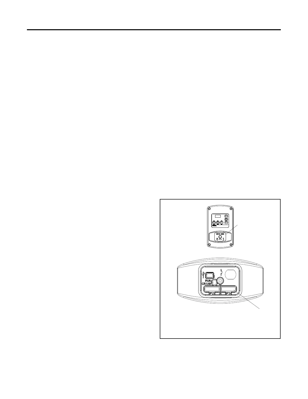
Identification and explanation of controller user interfaces and indicators.

Faults

Explanation of fault codes, warnings, and shutdowns displayed by the controller.

Controller Configuration and Adjustment

Steps for configuring and adjusting controller settings and parameters.

Section 5 Component Testing and Adjustment

Voltage Adjustment

Procedures for adjusting generator output voltage and frequency.

Governor System

Testing and adjustment of the engine governor system for speed control.

Fault Shutdown Tests

Procedures to verify the operation of overspeed, overcrank, and LOP shutdowns.

Section 7 Wiring Diagrams

Schematic Diagram

Electrical schematic diagram for the generator set.

Related product manuals