TP-6735 7/17 61Section 5 Component Testing and Adjustment
5.3 Stator
The stator contains a s eries of coils of wire laid in a
laminated steel frame. The stator leads supply AC
voltage to the load and voltage regulator. Before testing
the stator, inspect it for heat discoloration and visible
damage to housing lead wires, exposed coil windings,
and exposed areas of frame laminations. Be s ure the
stator is securely fastened to the stator housing.
Note: Disconnect all stator leads before performing all
stator tests.
Hazardous voltage. Moving parts.
Will cause severe injury or death.
Operate the generator set only when
all guards and electrical enclosures
areinplace.
DANGER
High voltage test. Hazardous voltage will cause severe
injury or death. Follow the instructions of the test equipment
manufacturer when performing high-voltage tests on the rotor
or stator. An improper test procedure can damage equipment
or lead to generator set failure.
Short circuits. Hazardous voltage/current will cause
severe injury or death. Short circuits can cause bodily injury
and/or equipment damage. Do not contact electrical
connections with tools or jewelry while making adjustments or
repairs. Remove all jewelry before servicing the equipment.
Stator Continuity and Resistance Tests
1. Press the OFF button on the controller to turn off
the generator set and remove controller fuse F3.
2. Disconnect power to the battery charger.
3. Disconnect the generator set engine starting
battery, negative (--) lead first.
4. Disconnect all stator leads before performing all
stator tests.
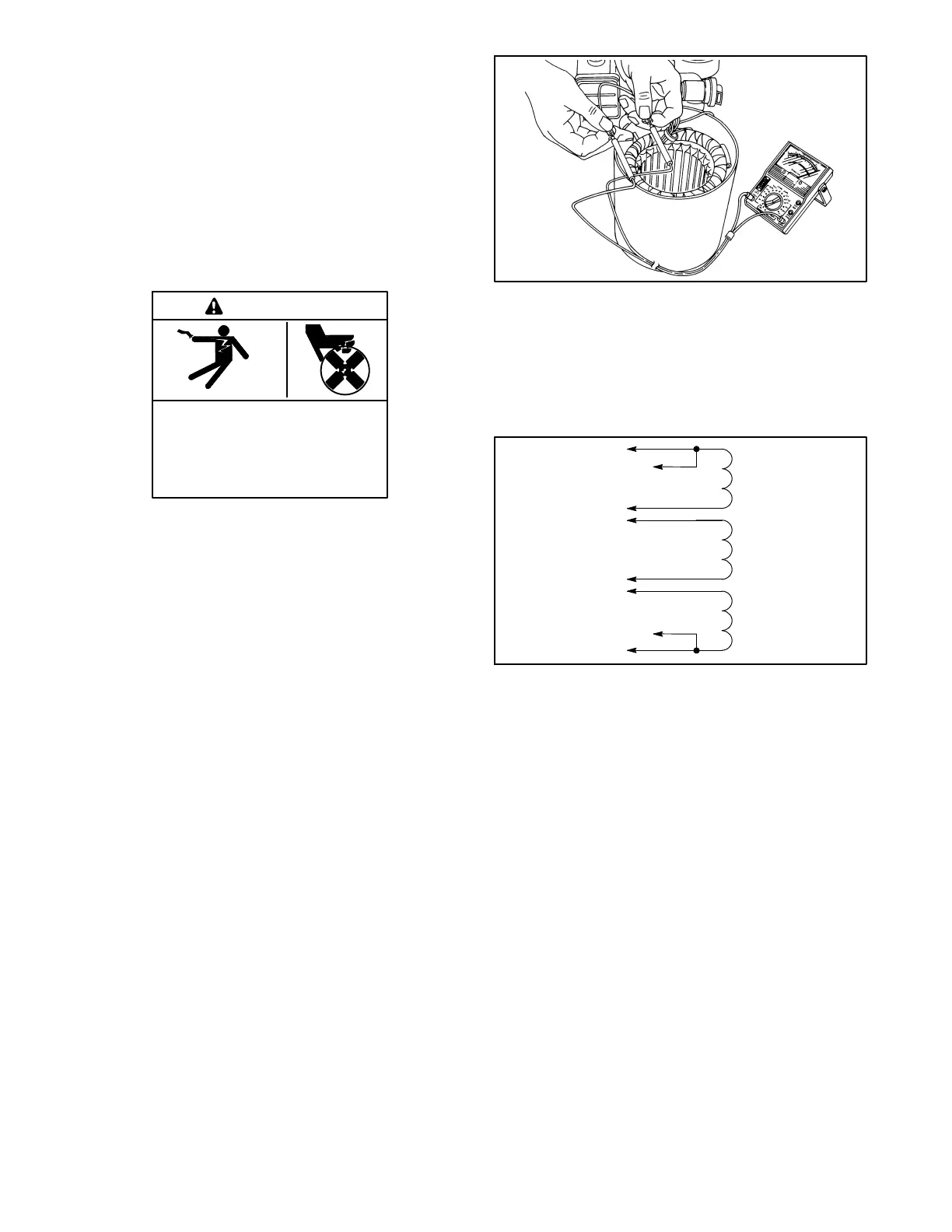
5. To check for stator continuity, set the ohmmeter on
R x 1 scale. First set the ohmmeter z ero by holding
the red and black meter leads together and setting
the ohmmeter reading to zero. Then check the
stator continuity by connecting the meter leads to
the stator leads as shown in Figure 5-4.
R14807-14
Figure 5-4 Testing Stator Windings
Note: For single-phase models. leads 1, 2, 3, and 4 are
the generator output leads. Leads 11, 44, 55, and
66 are the controller sensing and supply leads.
Refer to the schematic in Figure 5-5 when
performing the following steps.
3
4
55
2
1
44
11
6196
66
Figure 5-5 Single-Phase Alternator Stator Leads
6. Contact the ohmmeter leads and readjust the
ohmmeter to r ead zero ohms.
7. Check the cold resistance of the stator windings by
connecting the meter leads to stator leads 1-2, 3-4,
and 55-66. See Section 1.5, Alternator
Specifications, for stator winding resistances.
Most ohmmeters do not provide accurate readings
below 1 ohm. Low resistance readings (continuity)
and no evidence of shorted w indings (heat
discoloration) indicate a stator in good condition.
SeeFigure5-6.

 Loading...


