TP-6735 7/1738 Section 4 Controller
4.4 Controls and I ndicators
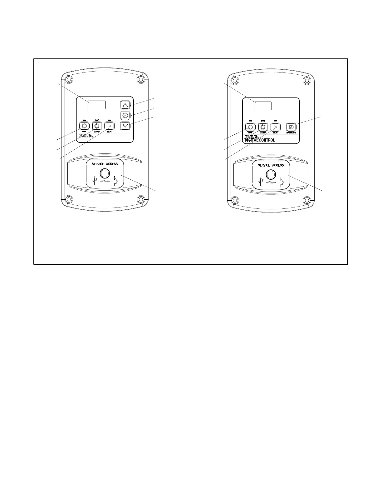
Figure 4-2 illustrates the RDC and DC controller user
interfaces.
1. LED display
2. Up button (RDC only)
3. Select button (RDC only)
4. Down/Exercise button (RDC)
5. Exercise button (DC)
6. Service access (see Section 3.3)
7. RUN button and LED
8. AUTO button and LED
9. OFF button and LED
1
9
3
2
7
8
6
4
1
9
7
8
6
5
Residential Digital Controller (RDC) Digital Controller (DC)
Figure 4-2 RDC and DC Controls and Indicators

 Loading...


